4–4
869 MOTOR PROTECTION SYSTEM – INSTRUCTION MANUAL
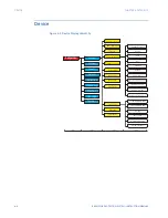
SETPOINTS MAIN MENU
CHAPTER 4: SETPOINTS
•
TDM
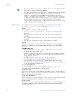
: The setting provides a selection for Time Dial Multiplier which modifies the
operating times per the selected inverse curve. For example, if an IEEE Extremely
Inverse curve is selected with TDM=2, and the fault current is 5 times bigger than the
PKP level, operation of the element can not occur before an elapsed time of 2.59 s
from Pickup.
•
OUTPUT RELAYS
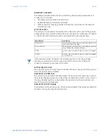
: The
<ELEMENT_NAME> RELAYS
setpoint selects the relays required
to operate when the feature generates an output. The range is “Operate” or “Do Not
Operate”, and can be applied to any combination of the auxiliary output relays. The
default setting is “Do Not Operate”.
The available auxiliary relays vary depending on the order code.
•
DIRECTION
: The
<ELEMENT_NAME> DIRECTION
setpoint is available for overcurrent
features which are subject to control from a directional element. The range is
“Disabled”, “Forward”, and “Reverse”. If set to “Disabled”, the element is allowed to
operate for current flow in any direction. There is no supervision from the directional
element. If set to “Forward”, the OC element is allowed to operate when the fault is
detected by the directional element in forward direction. In this mode, the OC element
does not operate for fault in reverse direction. If set to “Reverse”, the OC element is
allowed to operate when the fault is detected in reverse direction, and does not
operate in forward direction.
•
RESET
: Selection of an Instantaneous or a Timed reset is provided by this setting. If
Instantaneous reset is selected, the element resets instantaneously providing the
quantity drops below 97 to 98% of the PKP level before the time for operation is
reached. If Timed reset is selected, the time to reset is calculated based on the reset
equation for the selected inverse curve.
•
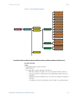
BLOCK
: The
<ELEMENT_NAME> BLOCK
setpoint selects an operand from the list of
FlexLogic operands, which when active, blocks the feature from running.
•
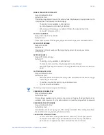
EVENTS
: The
<ELEMENT_NAME> EVENTS
setpoint can be set to “Enabled”, or
“Disabled”. If set to “Enabled”, the events associated with the pickup, operation, or
other conditions of the feature are recorded in the Event Recorder.
•
TARGETS
: The
<ELEMENT_NAME> TARGETS
setpoint can be set to “Disabled”, “Self-
Reset”, or “Latched”. If set to “Self-Reset”, or “Latched”, the targets associated with the
pickup, operation, or another condition of the feature are displayed on the screen of
the 869 relay. The targets disappear from the screen when “Self-Reset” is selected,
and the conditions are cleared. The targets stay on the screen, when “Latched” is
selected, and the conditions are cleared.
CAUTION:
To ensure the settings file inside the relay is updated, wait 30 seconds after a setpoint
change before cycling power.
FASTPATH:
When IP addresses are changed and sent as a Settings file the unit reboots twice.
Logic Diagrams
Refer to the logic diagrams provided for a complete understanding of the operation of
each feature. These sequential logic diagrams illustrate how each setpoint, input
parameter, and internal logic is used in a feature to obtain an output. In addition to these
logic diagrams, the Setpoints chapter provides written descriptions for each feature.
•
Setpoints
: Shown as a block with a heading labeled ‘SETPOINT’. The exact wording of
the displayed setpoint message identifies the setpoint. Major functional setpoint
selections are listed below the name and are incorporated in the logic.
•
Comparator Blocks
: Shown as a block with an inset box labeled ‘RUN’ with the
associated pickup/dropout setpoint shown directly above. Element operation of the
detector is controlled by the signal entering the ‘RUN’ inset. The measurement/
Summary of Contents for 869
Page 10: ...VIII 869 MOTOR PROTECTION SYSTEM INSTRUCTION MANUAL ...
Page 127: ...CHAPTER 3 INTERFACES SOFTWARE INTERFACE 869 MOTOR PROTECTION SYSTEM INSTRUCTION MANUAL 3 49 ...
Page 129: ...CHAPTER 3 INTERFACES SOFTWARE INTERFACE 869 MOTOR PROTECTION SYSTEM INSTRUCTION MANUAL 3 51 ...
Page 538: ...4 406 869 MOTOR PROTECTION SYSTEM INSTRUCTION MANUAL TESTING CHAPTER 4 SETPOINTS ...
Page 578: ...6 22 869 MOTOR PROTECTION SYSTEM INSTRUCTION MANUAL FLEXELEMENTS CHAPTER 6 METERING ...
Page 592: ...7 14 869 MOTOR PROTECTION SYSTEM INSTRUCTION MANUAL CLEAR RECORDS CHAPTER 7 RECORDS ...


