CHAPTER 4: SETPOINTS
PROTECTION
869 MOTOR PROTECTION SYSTEM – INSTRUCTION MANUAL
4–149
Loss of Excitation (40)
Typically, a synchronous machine has an excitation system, which supplies DC (Direct
Current) to energize the rotor/field winding. This excitation to the machine rotor may be
completely or partially lost due to various abnormal conditions, such as field circuit open
or short, loss of supply to the excitation system, or unintentional trip of a field breaker and
so on. Due to loss of excitation, the synchronous machine may act as an induction
machine, which may cause the machine to over-speed (above synchronous speed) and
also draw reactive power (Var) from the system. Therefore, Loss Of Excitation (LOE)
protection is applied to protect synchronous machines from over-speeding, as well as to
recover systems from voltage collapse.
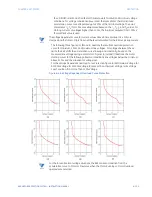
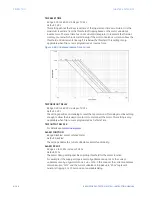
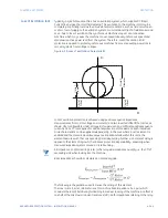
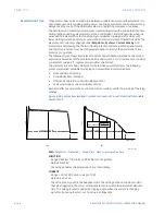
Figure 4-52: Loss of excitation Characteristic
Loss of excitation protection is achieved using positive sequence impedance
measurements (from J-slot voltage and currents), and two inverted offset (Mho) circles, as
shown. User configurable Under-Voltage (UV) supervision and sufficient positive sequence
current (>0.05 x CT) are applied for additional protection of this element. Each individual
circle characteristic can be applied independently. In the case where a circle element is
enabled and the measured positive sequence impedance falls within this circle, the
element operates with the corresponding time delay setting. Further, a 20 ms reset delay is
applied to the element logic which enhances protection dependability, especially when
measured impedance jitters around a circle boundary.
NOTE
NOTE:
All impedance (in ohms) settings refer to the relay side impedance quantity, i.e. the CT/VT
secondary side when looking into the machine.
Base impedance should be calculated on secondary side.
The following is the guideline used to derive the setting of this element.
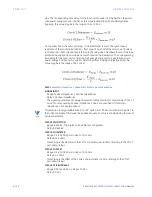
The inner circle (Circle 1) diameter is set to machine base impedance (i.e. 1 pu), which
considers the loss of field during full loading to medium loading of the machine. An offset is
one half of the direct axis transient reactance (X'd) - both impedances referring to the relay
Circle 1
Diameter
Circle 2
Diameter
R
X
Circle 1
Offset
Circle 2
Offset
Summary of Contents for 869
Page 10: ...VIII 869 MOTOR PROTECTION SYSTEM INSTRUCTION MANUAL ...
Page 127: ...CHAPTER 3 INTERFACES SOFTWARE INTERFACE 869 MOTOR PROTECTION SYSTEM INSTRUCTION MANUAL 3 49 ...
Page 129: ...CHAPTER 3 INTERFACES SOFTWARE INTERFACE 869 MOTOR PROTECTION SYSTEM INSTRUCTION MANUAL 3 51 ...
Page 538: ...4 406 869 MOTOR PROTECTION SYSTEM INSTRUCTION MANUAL TESTING CHAPTER 4 SETPOINTS ...
Page 578: ...6 22 869 MOTOR PROTECTION SYSTEM INSTRUCTION MANUAL FLEXELEMENTS CHAPTER 6 METERING ...
Page 592: ...7 14 869 MOTOR PROTECTION SYSTEM INSTRUCTION MANUAL CLEAR RECORDS CHAPTER 7 RECORDS ...

