


Installation
750/760 Quick Reference Guide
53
1.
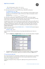
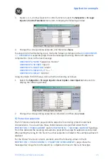
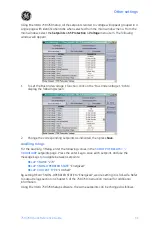
Select the
Setpoints > S3 Logic Inputs > Logic Input Setup
menu item. The following
window will appear:
2.
Change the corresponding setpoints as indicated, then press
Save
. These setpoints
are only used to identify the Logic Inputs and define their asserted logic.
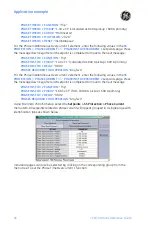
To complete the setpoints corresponding to logic inputs, define their functionality as
follows.
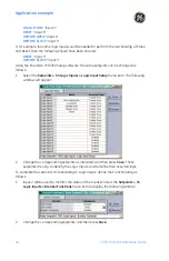
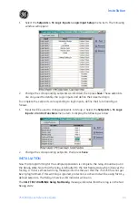
1.
Input 8 will be used to change setpoints to Group 2. Select the
Setpoints > S3 Logic
Inputs > Control Functions
menu item to display the following window:
2.
Change the corresponding setpoints, then press
Save
.
INSTALLATION
Now that programming for the sample application is complete, the relay should be put in
the Ready state. Note that the relay is defaulted to the Not Ready state when it leaves the
factory. A minor self-test warning message informs the user that the 750/760 has not yet
been programmed. If this warning is ignored, protection is active and will be using factory
default setpoints. The Relay In Service LED Indicator will be on.
The
SELF TEST WARNING: Relay Not Ready
message indicates that the relay is in the Not
Ready state
Summary of Contents for 750
Page 2: ......
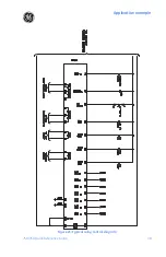
Page 39: ...Application example 750 760 Quick Reference Guide 35 Figure 17 Typical three line diagram...
Page 41: ...Application example 750 760 Quick Reference Guide 37 Figure 19 Typical control diagram...
Page 42: ...Application example 38 750 760 Quick Reference Guide Figure 20 Typical breaker control diagram...
Page 43: ...Application example 750 760 Quick Reference Guide 39 Figure 21 Typical relay control diagram...


