
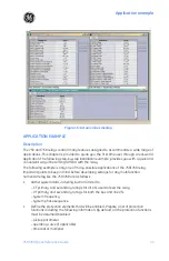


Application example
40
750/760 Quick Reference Guide
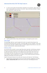
Power system data
The power system data for the application example is shown below.
•
System: three-phase, four-wire
•
Frequency: 60 Hz
•
Line-to-line voltage: 13.8 kV
•
Maximum current: 600 A
The above data will be used to set the relay system parameters.
Control system requirements
1.
All protection elements used are to trip the breaker.
2.
Breaker position monitoring via 52b contact only.
3.
Only current metering is required.
4.
Contact Inputs: Remote open and close contacts from RTU.
5.
Remote/local selection from panel hand switch. Reset from RTU.
6.
Alarm after 100 second delay from substation monitor. This is normally used to signal
the remote center when someone has gained access to the substation.
7.
Contact Outputs:
•
Trip and close to breaker control circuit (trip and close relays).
•
Relay failure alarm to RTU (self-test warning, no programming required).
•
Alarm contact to RTU (setup in User Function for “Substation Monitor”)
•
No data communications to other equipment.
The above data will be used to set the output relays to achieve breaker control and to set
digital inputs for breaker status, remote operations, remote status, and alarm indication.
The example assumes that the communications between the station and the master
control center will be done by the RTU. Alarms, status indication, and breaker commands
will be hard-wired from the relay to the RTU. Please note that, similar information could be
exchanged between the RTU and the relay via an RS485 or RS422 serial link using Modbus
RTU protocol. Refer to GE Publication
GEK-106473C: 750/760 Communications Guide
for
additional information.
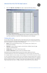
Instrument transformer data
1.
Bus VTs: 2
×
Delta connected, ratio = 14.4 kV:120 V
2.
Phase CTs: 3
×
Wye connected, ratio = 600:5 A
The above data will be used to set the relay system parameters, such as CT and VT
connections, VT secondary voltage, and CT and VT primary to secondary ratios.
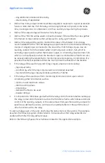
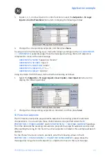
Phase protection settings
1.
Time Overcurrent 1 (51P1): Curve Shape = Moderately Inverse; Pickup = 840 A;
Multiplier = 20.2
2.
Instantaneous Overcurrent 1 (50P1): Pickup = 840 A; Phases Required = Any Two;
Delay = 0 s
3.
Instantaneous Overcurrent 2 (50P2): Pickup = 10100 A; Phases Required = Any Two;
Delay = 0 s
Summary of Contents for 750
Page 2: ......
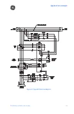
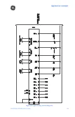
Page 39: ...Application example 750 760 Quick Reference Guide 35 Figure 17 Typical three line diagram...
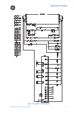
Page 41: ...Application example 750 760 Quick Reference Guide 37 Figure 19 Typical control diagram...
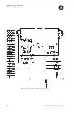
Page 42: ...Application example 38 750 760 Quick Reference Guide Figure 20 Typical breaker control diagram...
Page 43: ...Application example 750 760 Quick Reference Guide 39 Figure 21 Typical relay control diagram...


