Application example
42
750/760 Quick Reference Guide
(for a 138 kV system, 13.8 kV / 120 = 115 V)
VT RATIO
: “120:1” (14.4 kV VT
primary
/ 120 V VT
secondary
)
For the case where Bus VTs are connected in Wye, the system settings are:
VT CONNECTION TYPE
: “Wye”
NOMINAL VT SECONDARY VOLTAGE
: “66.4 V” (the phase-to-neutral voltage must be
entered. For a 13.8 kV system, we have 13.8kV ø-ø
≡
7.97kV ø-N; therefore, 7.97kV /
120 = 66.4 V)
VT RATIO
: “120:1” (14.4 kV VT
primary
/ 120V VT
secondary
)
The 750/760 was designed to display primary system values. Current and voltage
measurements are performed at secondary levels, which the relay transforms to primary
values using CT and VT ratios, as well as nominal secondary values.
Configuring the relay for current measurement is simple and it only requires setting the CT
ratios. CT inputs can be 1 A or 5 A and must be specified when the relay is purchased. There
is additional flexibility with regards to the VT inputs, as nominal values are not required
before the relay is ordered; therefore, more settings are needed to prepare the relay for
voltage measurements.
Make the following change in the
S2 SYSTEM SETUP
ZV
POWER SYSTEM
setpoints page to
reflect the power system:
NOMINAL FREQ
: “60 Hz”
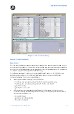
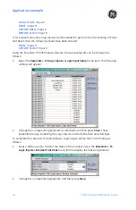
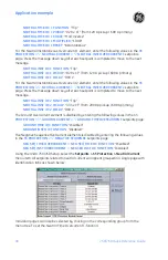
Using EnerVista 750/760 Setup software, the settings described above can be set as
follows:
1.
Select the
Setpoints > S2 System Setup
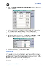
menu item. The following window will appear:
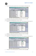
2.
Change the values of phase CT primary, VT connection type, nominal VT secondary
voltage, VT ratio, and system frequency as required, then press the
Save
button.
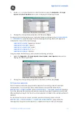
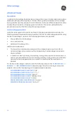
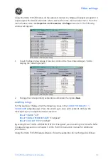
S3 Logic Inputs setpoints
The S3 setpoints page is for entering the characteristics of the logic inputs. In our example,
these characteristics are specified under the Control System Requirements heading.
Program the S3 setpoints as indicated.
To properly configure the relay to respond to digital inputs, they need to be defined as
follows:
Summary of Contents for 750
Page 2: ......
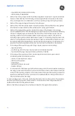
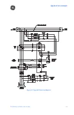
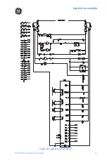
Page 39: ...Application example 750 760 Quick Reference Guide 35 Figure 17 Typical three line diagram...
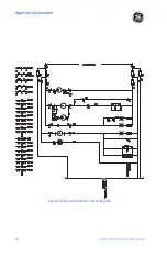
Page 41: ...Application example 750 760 Quick Reference Guide 37 Figure 19 Typical control diagram...
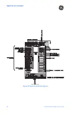
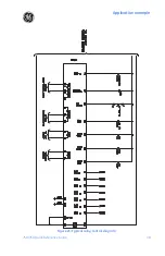
Page 42: ...Application example 38 750 760 Quick Reference Guide Figure 20 Typical breaker control diagram...
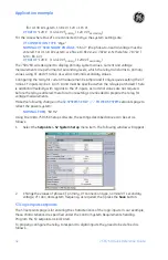
Page 43: ...Application example 750 760 Quick Reference Guide 39 Figure 21 Typical relay control diagram...

