26
Operation
Utility Voltage Pickup Sensor
This sensor monitors utility voltage. When utility voltage is
restored above 80 percent of the nominal source voltage,
a time delay starts timing and the engine will go to engine
cool-down.
Engine Cool‑down Timer
When utility power is sensed and the load transfers back to
the utility source, the engine will go into a cool down period
as described below:
• If the generator has run for MORE than 5 minutes,
once the utility transfer occurs, the engine will
continue to run for about 1 minute before shutting
down.
• If the generator has run for LESS than 5 minutes, once
the utility transfer occurs, the engine will continue to
run until 5 minutes has elapsed before shutting down.
The transfer switch monitors utility voltage. Should utility
voltage drop below a preset level, the transfer switch will
signal the engine to crank and start.
When utility voltage is restored above a preset voltage level,
the engine is signaled to shut down.
The actual system operation is not adjustable and is
sequenced by sensors and timers on the transfer switch,
as follows:
Utility Voltage Dropout Sensor
• This sensor monitors utility source voltage.
• If utility source voltage drops below about 70 percent
of the nominal supply voltage, the sensor energizes
a 3 second timer. The timer is used to ‘sense’
brown-outs.
• Once the timer has expired, the engine will crank
and start.
Automatic Operation Sequence
Setting Exercise Timer
It is recommended to have the generator go through an
excercise cycle once every seven days. During this exercise
period, the unit runs for approximately 20 minutes and then
shuts down.
Refer to the
Control Panel Application Guide
supplied with
this generator for more detailed information on the exercise
timer.
OR, refer to the Automatic Transfer Switch Application Guide
for more detailed information on the exercise timer.
NOT
for
REPRODUCTION
Summary of Contents for 60000 Series
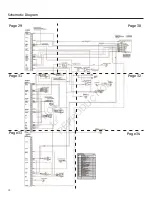
Page 35: ...35 N O T f o r R E P R O D U C T I O N...
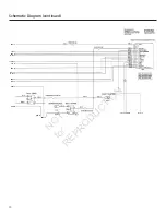
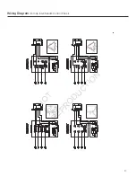
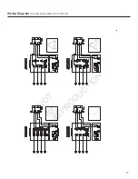
Page 36: ...36 Wiring Diagram ComAp InteliNano Control Panel N O T f o r R E P R O D U C T I O N...
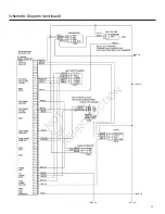
Page 37: ...37 Wiring Diagram ComAp InteliNano Control Panel N O T f o r R E P R O D U C T I O N...
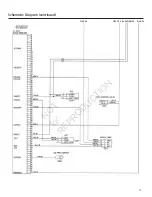
Page 38: ...38 Wiring Diagram ComAp InteliLite Control Panel N O T f o r R E P R O D U C T I O N...
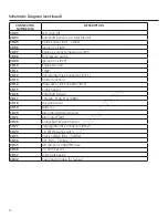
Page 39: ...39 Wiring Diagram ComAp InteliLite Control Panel N O T f o r R E P R O D U C T I O N...

