


GE
Direction 5370626-100, Revision 18 LOGIQ e/LOGIQ e Vet/LOGIQ i/Vivid e Basic Service Manual
Chapter 3 System Setup
3-17
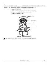
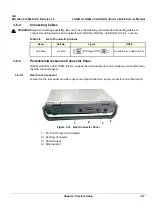
3-6-4
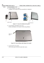
Connecting Cables
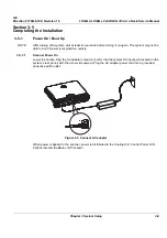
3-6-5
Peripherals/Accessories Connector Panel
LOGIQ e/LOGIQ e Vet/LOGIQ i/Vivid e peripherals and accessories can be properly connected using
the side connector panel.
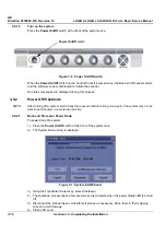
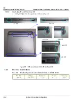
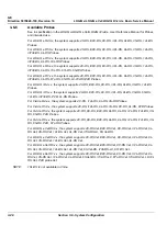
3-6-5-1
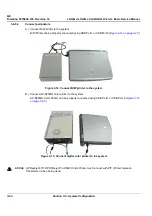
Rear Panel Connector
Located on the rear panel are video input and output connectors, power connector and ethernet port.
1.) Port for DC input (AC Adapter)
2.) Docking Connector
3.) SVGA Output
4.) Ethernet port
WARNING
WARNING
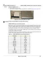
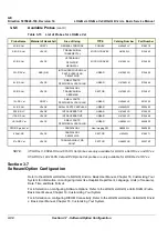
Equipment damage possibility. Be sure to use the following recommended connecting cables to
connect recording devices and a network with LOGIQ e/LOGIQ e Vet/LOGIQ i/Vivid e console.
Table 3-8
List of Connecting Cables
Name
Part No.
Figure
NOTE
USB Cable
5122305
For USB Printer & USB DVD-RW
Figure 3-12 Rear Connector Panel
4
3
2
1
Summary of Contents for 5151219
Page 271: ......