


GE
Direction 5370626-100, Revision 18 LOGIQ e/LOGIQ e Vet/LOGIQ i/Vivid e Basic Service Manual
5-6
Section 5-3 - Power Diagrams
Section 5-3
Power Diagrams
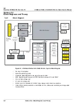
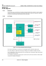
5-3-1
Overview
The AC Power assy’s main tasks are to isolate and output to the DC/DC unit which is inside the system
console. The input of AC power pack will be the AC outlet and it’s universal, the range is AC 90V-264V,
47-63Hz. And no main power switch located on this power pack.
5-3-2
AC Power
The mains cord has plugs in one side end. A male plug connects to the mains outlet on site.
The mains voltage is routed to the AC power pack through a Circuit Breaker located on the site.
The Circuit Breaker is of the auto fuse type, if for some reason the current grows to high, the switch will
automatically break the power.
From the Main Circuit Breaker, the AC power is routed via an Inrush Current Limiter to a internal outlet
connector for the Mains Transformer.
Figure 5-4 AC Power Distribution Block Diagram
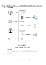
TMST & TX64
Summary of Contents for 5151219
Page 271: ......