


GE
Direction 5370626-100, Revision 18 LOGIQ e/LOGIQ e Vet/LOGIQ i/Vivid e Basic Service Manual
5-2
Section 5-2 - Block Diagrams and Theory
Section 5-2
Block Diagrams and Theory
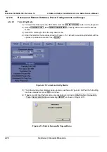
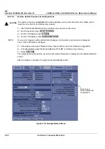
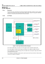
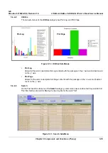
5-2-1
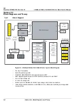
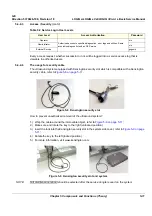
Block Diagram
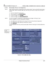
•
Pre Amp: Preamplifier
•
OQX2: Beamforming ASIC
•
CHACOM: B/M/CFM/DOP mode signal processor ASIC
•
DSP: Digital Signal Processor with PCI interface between CPU and TMST
•
HV unit: High voltage unit
•
LV unit: Low voltage unit
•
DC/DC & HV Ctrl, SMBUS I/F: DC/DC high voltage control smart bus interface
•
TUSC FPGA: LOGIQ e/LOGIQ e Vet/LOGIQ i/Vivid e Ultrasound controlling and Image data
transfer FPGA
Figure 5-1 LOGIQ e/LOGIQ e Vet/LOGIQ i/Vivid e System Block Diagram
P
robe
C
o
nn
ec
to
r
TX64
RX64
TMST(RFI/Carrier)
HV unit
Battery Charger
and MUX
AC
Adapter
Li-Ion
Battery
Keyboard
A/N key
Trackball
U/S key
TGC
Soft menu key
LCD
15” XGA
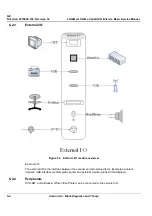
I/O
Peripherals
USB2.0
Ethernet
VGA
Docking
Audio
Speaker
DVD-RW
USB-Wireless
LAN
Printer
Limited backlit
ECG
Foot SW
VCR
Cart
SMBus
PS2
USB
64
128
CWD
(option)
USC
LV unit
On board
Distributed
Power
Summary of Contents for 5151219
Page 271: ......