GDS GASMAX ECx Operation & Maintenance Manual Download Page 24

GASMAX ECx Instruction Manual  


Revision 1.1 


24

7.2 

Set Gain to Unity (Technicians only!): 

Set Gain to UNITY

 allows resetting previous calibration OFFSET to zero and GAIN to one.  This 

is the definition of UNITY.  A calibration should be performed after setting UNITY. 

*****WARNING*****

Previous Calibration

will be erased.

 EDIT to confirm.

 NEXT to exit.

Gain=Unity

EDIT


Figure 7-2: Set UNITY GAIN Menu 

7.3 

PreAmp Gain Adjust (Technicians only!): 

Depending upon 

Input Type

, GM ECX inputs range from a few micro amps to hundreds of micro 

amps.  

PreAmp Gain Set

 is the adjustment that matches the input signal range to the GM ECX 

input signal conditioning circuits.  Altering the PreAmp Gain setting automatically resets previous 
calibration OFFSET & GAIN values to UNITY as described in section 7.2. 

If it is determined the PreAmp Gain value is incorrect, apply the desired up-scale input and use 
the UP / DOWN keys to obtain the correct 

Reading

 value.  

Counts

 are the 10-bit binary A/D 

value with an active range value of 0 - 1023. 

CAUTION:

  For standard installations, this is a factory adjustment.  Do not use the 

PreAmp Gain 

Set

 menu for calibrating sensors.  It should only be adjusted if a new measurement gas or input 

range is required. 

PGA Setup

Gain     25.0%

Counts   1011

Reading  100

Up/Dn to Change.

Next to exit.


Figure 7-3: PreAmp Gain Adjust (PGA) Menu 

7.4 

Simple Sensor Input Type (Technicians only!): 

Smart

 sensors automatically configure 

Input Type. 


Simple

 inputs must be configured manually 

using the 

Input Type

 menu.  

Input Type

 configures GM ECx hardware to accept positive or 

negative coefficient electrochemical sensors.  Positive / Negative coefficient electrochemical 
sensors have several gas types available within each group (see table below).  Biased EC 
sensors require factory installed solder bridge SB1 on the Display Assy PCB - see Addendum 3. 
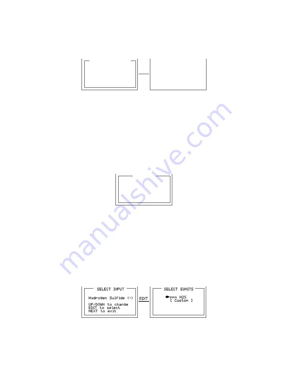
After selecting 

Input Type

, a 

SELECT EUNITS

 screen indicates the default engineering units for 

this sensor.  These EUNITS may be accepted by pressing the EDIT key, or changed by moving 
the pointer to [Custom] and editing as described in 

Configuration Using the Magnetic Wand

 in 

section 6-2. 


Figure 7-4: “Simple” Sensor Input Type Selection Menu 

Summary of Contents for GASMAX ECx

Page 1: ...mart Sensor Interface Important Read and understand contents of this instruction manual prior to use Improper use of equipment could result in instrument malfunction or serious injury GDS Corp 2513 Hwy 646 Santa Fe Texas 77510 409 927 2980 409 927 4180 FAX www gdscorp com tech gdscorp com ...

Page 2: ...and GM ECX Signal Conditioning 13 SECTION 4 INITIAL START UP 13 4 1 Transmitter Configuration Menu 13 4 2 Initial Toxic Oxygen Monitor Start Up 13 4 2 1 Initial Toxic Oxygen Monitor Span Check 14 SECTION 5 OPERATING INSTRUCTIONS 14 5 1 CAL MODE Routine Sensor Calibrations 14 5 2 ALARM OPERATION 16 5 2 1 ALARM 3 UNDERSTANDING FAULT LEVEL OPERATION 16 SECTION 6 SETUP MENU CONFIGURATION 17 6 1 Menus ...

Page 3: ...Cx Periodically test for correct operation of the system s alarm events by exposing the monitor to a targeted gas concentration above the High Alarm setpoint Do not expose the GM ECx to electrical shock or continuous severe mechanical shock Protect the GM ECx from dripping liquids and high power sprays Use only for applications described within this manual CAUTION FOR SAFETY REASONS THIS EQUIPMENT...

Page 4: ...ature allows event logging of calibrations and alarm trips for review on the LCD readout Compatible sensors include an 8 wire Smart Sensor interface capable of configuration data uploads to the monitor as well as traditional Simple sensors with three wire interface A separate PC compatible USB Interface device part 10 0252 allows Smart sensors to be preloaded with configuration variables via a PC ...

Page 5: ...l 0 32 and System ID 0 255 to communicate see section 6 7 There should never be two servers with the same Hop Channel System ID settings in the same coverage area The Server must be in a powered location and should be centrally located since all Clients must receive the server s beacon in order to communicate Correct planning and design of wireless systems are imperative for ensuring a successful ...

Page 6: ... the radio to transmit Five minutes or fifty sequential reads when there is no A1 or A2 alarm Any receiving controller will report a Communications Error if the GM ECx does not reply for periods of greater than 18 minutes A3 and FAIL alarms do not increase radio transmission rates Every six seconds if there is an A1 or A2 level alarm Upon entry into CAL mode a value of 75 15 6 scale is transmitted...

Page 7: ...0291 The 10 0291 RF module mounts piggy back to the back of the Display assembly as shown in Figure 2 3 The MMCX RF connector connects to the antenna fitting s pigtail coax cable There is also a slender 4 conductor cable between the 10 0291 and the 10 0299 battery I O PCB bolted to the bottom of the enclosure ...

Page 8: ...there are no significant currents Lighter than air gases should have the monitors mounted 12 18 inches 30 45 centimeters above the potential gas leak and heavier than air gases should be this distance below Even though the GM ECx is designed for rugged service sensors should be protected from environmental damage from water snow shock vibration and dirt 3 3 Mounting the Enclosure The GM ECx standa...

Page 9: ...ounting flanges WARNING Qualified personnel should perform the installation according to applicable electrical codes regulations and safety standards Insure correct cabling and sealing fitting practices are implemented Do not aim the sensor pointing upward Install the GM ECx to a wall or bracket using the predrilled mounting flanges with I D 0 25 on 5 5 inch centers Figure 3 1 If conduit is rigid ...

Page 10: ...sses in the system For best RF line of site the combined height of both antennas must exceed the Fresnel zone diameter see below Dist between ant s Fresnel zone diameter Freespace loss dB 1000 ft 300 m 16 ft 4 9 m 81 1 Mile 1 6 km 32 ft 9 7 m 96 5 miles 8 km 68 ft 20 7 m 110 10 miles 16 km 95 ft 29 m 116 Example The RF900 radio modem has the following parameters Maximum RF900 TX power setting 30 d...

Page 11: ...wiring into TB2 of the 10 0232 Display Assembly see Figure 3 4 The 10 0247 s Smart Sensor cable connects to S1 of the 10 0232 Display Assembly see Figure 3 4 This unique Smart Sensor Interface may be used to configure smart sensors and or GM ECX s from a PC rather than entering all variables via the magnetic keypad Sensors used with the smart sensor head see Figure 3 5 are considered smart since t...

Page 12: ...is shown after power up upon installation of a new smart sensor or by viewing INPUT type in the SENSOR SETTINGS INFO menu section 5 5 SMART SENSOR Type Cat Bead Span 100 Zero 0 SN xxxxxx Born On 01 28 04 Last Cal 04 05 04 ANY key to Exit ERROR CODE 01 Incorrect Sensor installed Install correct sensor or update transmitter SEE MANUAL EDIT key to update Any other to abort If installed sensor type do...

Page 13: ...ECTION 4 INITIAL START UP 4 1 Transmitter Configuration Menu Figure 4 1shows the GM ECX XMITTER CONFIG menu used to activate channels precisely calibrate 4 20mA outputs and set time date Its menus are set at the factory and typically not needed by the user To access from any data display press and hold the NEXT key for 5 seconds until the screen appears requesting a special key sequence 4 UP keyst...

Page 14: ...it output indicates CAL MODE by transmitting 75 counts It then transmits 200 counts during the subsequent CAL PURGE delay to prevent external alarms during calibration CAL MODE automatically exits if no keystrokes are detected after 5 minutes The GM ECx wireless 10 bit output range is 200 to 1000 counts for 0 to 100 of full scale The GM ECx indicates CAL MODE by transmitting 75 counts 15 6 FS to r...

Page 15: ...calibration WARNING The SPAN gas used must match the value specified since this is what the GM ECX will indicate after a successful SPAN calibration The Cal Span Value may be edited if it becomes necessary to apply a different gas concentration see Cal Span Value in section 3 4 5 If the SPAN calibration is successful the display flashes REMOVE CAL GAS and starts the CAL PURGE delay see section 6 6...

Page 16: ...ffset Gain constants Measurement Name LEL 2 Measurement Name LEL 0 PGA xxxx Figure 5 2 Cal Mode Flow Chart and Menus 5 2 ALARM OPERATION GM ECX s have front panel LED indicators for Alarm 1 Alarm 2 and FAIL CAUTION GM ECX Alarm LED indicators function even without the presence of the 10 0234 Relay option With battery power operation to conserve power alarm LED s only flash during alarm events 5 2 ...

Page 17: ...each unit The Educator allows configuring up to six GM ECx s at the PC and transporting their configuration data to each location This is useful when numerous installed units must be configured The GM ECx s configuration menus are shown in Figure 6 1 Figure 6 1 Configuration Menu Tree 6 2 Configuration Using the Magnetic Wand Passing the magnetic wand past the EDIT key from either data display dis...

Page 18: ... to be displayed when 20mA 100 is the GM ECX output The highest reading allowed is 9999 includes negative polarity sign and one decimal point Polarity is only indicated for negative readings Decimal Points sets the resolution of the LCD readings and may be for 0 1 or 2 Example ZERO readings for 0 1 2 DP s respectively are 0 0 0 0 00 Cal Span Value sets what upscale value must be applied when perfo...

Page 19: ...ge in this direction A3 has a default negative 5 of range Set Point with Low Trip set for YES This makes it function as a FAULT alarm and trip when the monitored value is more than 5 out of range Dead Band has a minimum value of 1 and a maximum value of 10 It is useful for preventing alarm cycling when the monitored value is hovering around the set point EXAMPLE With a range of 0 100 ppm if Dead B...

Page 20: ...u is therefore not available with a smart sensor connected Recall Cal History recalls each successful calibration These dates may be reviewed by scrolling with the UP DOWN keys Input Type indicates what kind of input or sensor the GM ECX is configured to accept and is typically pre configured at the factory There are three Input Type possibilities consisting of simple EC negative simple EC positiv...

Page 21: ...e RTU address for this particular GM ECx Controller channels receiving this monitor s data must also be configured with this matching Remote ID address System ID may be set from 1 255 and is similar to a password character or network number and makes network eavesdropping more difficult A transceiver will not go In Range of or communicate with a transceiver operating on a different System ID TX Po...

Page 22: ...ineering unit range should be 0 5 00 VDC Even if this channel reads VALUE from the GM ECx the battery voltage is displayed at the bottom of this C1 menu as shown in Figure 6 8 Figure 6 8 C1 Base Station Data From Menu 6 8 SYSTEM SECURITY The SYSTEM SECURITY menu offers two levels of protection A LOW level allows CAL MODE sensor calibrations but requires the 4 digit Pass Code prior to altering menu...

Page 23: ...these menus Back up the current configuration prior to altering any Technical menus in case Restore is required later see section 6 3 The TECHNICIAN ONLY menu group in Figure 7 1 contains items that are factory configured depending upon the type sensor and input connected to the GM ECX They should not be tampered with after installation If configured incorrectly some items will prevent monitoring ...

Page 24: ...ve range value of 0 1023 CAUTION For standard installations this is a factory adjustment Do not use the PreAmp Gain Set menu for calibrating sensors It should only be adjusted if a new measurement gas or input range is required PGA Setup Gain 25 0 Counts 1011 Reading 100 Up Dn to Change Next to exit Figure 7 3 PreAmp Gain Adjust PGA Menu 7 4 Simple Sensor Input Type Technicians only Smart sensors ...

Page 25: ...y The Zero Cal Value menu entry allows the zero calibration value to be set for something other than a zero reading In rare cases it may be necessary to perform Zero calibrations at some other engineering unit reading than zero Do not exceed 25 of full scale 7 6 Raw Min Max Counts Technicians only The Raw Min Max Counts menus determine the range of 10 bit analog to digital A D converter counts tha...

Reviews: