background image


AR-24 User Manual


Installation                                       2-22 

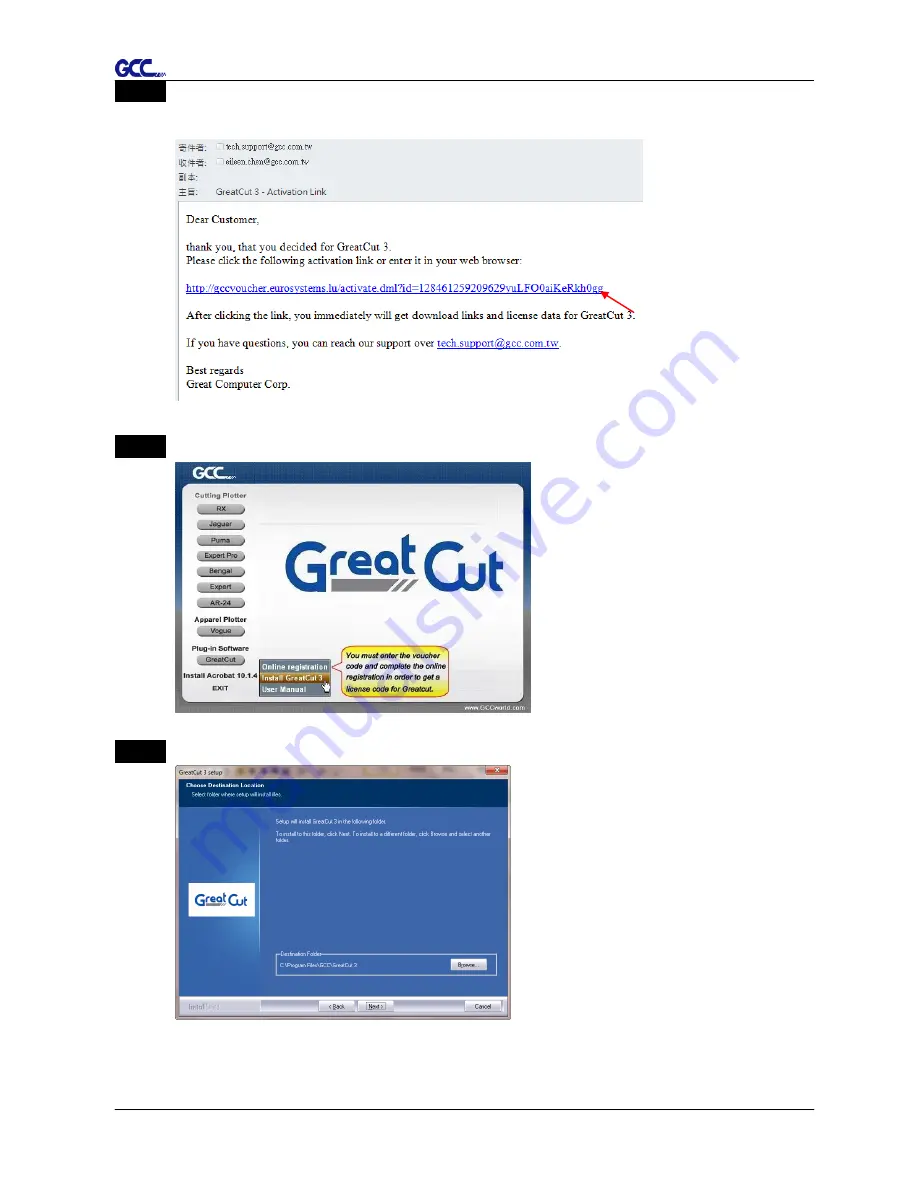
Step 5 

Check your email to see if you receive the activation link and click the link that will 

direct you the link for GreatCut download. 


Step 6 

Click “Install GreatCut” in installation DVD. 


Step 7 

Select a destination folder.


Summary of Contents for AR-24

Page 1: ...V 10 2018 Mar AR 24 User Manual http www GCCworld com...

Page 2: ...fy the information contained in this user manual at any time without prior notice un authorised modification copying distribution or display is prohibited All comments queries or suggestions concernin...

Page 3: ...tip can fly out During an operation do not touch any of the moving parts of this machine such as the carriage Also be careful to make sure that clothing and hair do not get caught Always connect the...

Page 4: ...cutter 2 11 2 5 1 2 Installing the driver 2 11 2 5 1 3 Driver Un installation 2 14 2 5 2 RS 232 Interface 2 17 2 5 3 Data Transmitting 2 18 2 5 4 Printer Sever Shared Setting 2 18 2 6 Software Instal...

Page 5: ...e of Contents 5 Trouble Shooting 5 1 What if AR 24 cannot Operate 5 1 5 2 Cutting Quality Problems 5 2 Appendix A 1 AR 24 Specification A 1 A 2 Blade Specification A 2 A 3 CorelDraw Instruction A 3 A...

Page 6: ...al dealer for further assistance 1 2 Product Features The followings are the main features of the AR 24 cutting plotters Dual port connectivity USB Serial interface Up to 250 gram cutting force Up to...

Page 7: ...h clear guideline marks D Tool Carriage To help perform cutting job with installed blade or pen E Blade Holder To hold the blade F Platen The surface for holding and supporting media in operation G Cu...

Page 8: ...Object Description K Serial Interface Connector To connect the machine with a computer through a RS 232 cable L USB Connector To connect the machine with a computer through a USB cable M AC Power Con...

Page 9: ...he relative humidity between 25 and 75 in the workshop Protecting the machine from dust and strong air current Preventing the machine from direct sunlight or extremely bright lighting Notice 3 Connect...

Page 10: ...for assembling the stand and the media support system Step 1 Please examine the supplied items in the accessory box of the carton before you install Stand is a standard item for AR 24 Item List Beam x...

Page 11: ...he vertical stands and beam with screws L and flat washers Figure 2 1 Step 3 Position the assembled stands perpendicularly and tighten the assembled vertical stands to the bottom stands with screw L a...

Page 12: ...lder Roll media Step 4 Position the stand under the plotter and tighten the plotter onto vertical stands with screw S and flat washer Figure 2 3 Step 5 Insert the roll holder into the roll media Figur...

Page 13: ...4 User Manual Installation 2 5 Roll holder support Step 6 Place the roll holder with media onto the roll holder support Figure 5 Step 7 The complete picture will be shown below Figure 6 Figure 5 Figur...

Page 14: ...blade Figure 2 8 Push the blade to the bottom of the blade holder Figure 2 9 Step 3 Adjust the blade tip to suitable length by screwing Blade tip adjustment screw clockwise or count clockwise Figure 2...

Page 15: ...ing quality might be affected By increasing the cutting force it might do the trick However once the blade is worn out and no longer provides a reliable cutting you should replace a new one The blade...

Page 16: ...ront side or the backside The alignment rulers on the platen extension will help you to adjust the media precisely Figure 2 14 Step 3 Then move the pinch rollers manually to the proper position Be sur...

Page 17: ...ary Pinch Roller at the center of media Figure 2 17 Primary Pinch Roller Secondary Pinch Roller O Correct Figure 2 18 X Incorrect NOTE Always adjust the position with the pinch rollers released raised...

Page 18: ...ading 2 4 3 How to change the poll size without turning off the machine Press origin set twice and the machine will start moving to get the new size Then open the VLCD and under the poll size you will...

Page 19: ...CC cutter 1 Turn on the machine 2 Connect the USB connector to the machine and then USB driver will installed automatically It will take a few minutes to find the device Please DO NOT disconnect the U...

Page 20: ...tic Detection or Windows Driver Win 7 and Above Manual Selection to start installing the Driver and AAS plug in Step 3 Click Next to start the driver installation Step 4 If you were Windows 7 and abov...

Page 21: ...running application programs before you start installing the driver and then click OK Step 7 The installation will take a few minutes to complete and you will see a message below and click on OK upon...

Page 22: ...3 Driver Un installation You have to remove previous version driver installed on your PC system completely before you can install the latest version successfully Please refer to below steps Step 1 Go...

Page 23: ...15 Step 2 After removing the unit click on any printer on the page and select Print server properties For Win 7 and above Or right click on blank space and then select Print server properties For Wind...

Page 24: ...nstallation 2 16 Step 4 Select the model and click on Remove Step 5 Select Remove driver and driver package and click OK Step 6 Click Yes and then click Delete and OK and the driver installed on PC is...

Page 25: ...are package refer to chapter 3 Misc key description 2 5 3 Data Transmitting There are two options to transmit the data from the computer to the cutting plotter Option 1 With proper interface settings...

Page 26: ...the printer driver as a shared printer then use B PC to connect A PC s printer driver via Intranet A PC B PC Step 1 Set A PC s printer driver as a shared printer Right click on printer icon choose Pri...

Page 27: ...lation 2 19 Step 2 Click Advanced tab then choose Print directly to the printer option Step 3 Send a job from A PC to the machine to check if A PC is connected to the machine Try to send a job to chec...

Page 28: ...5 Right click on the printer icon and select Connect to A PC s printer 2 6 Software Installation 2 6 1 GreatCut Installation Step 1 Click GreatCut Registration in installation DVD to go http gccvouche...

Page 29: ...o to registration page Step 3 Fill in the required information and click Request license code Step 4 The registration is completed you should receive two emails one is registration confirmation with a...

Page 30: ...n 2 22 Step 5 Check your email to see if you receive the activation link and click the link that will direct you the link for GreatCut download Step 6 Click Install GreatCut in installation DVD Step 7...

Page 31: ...23 Step 8 Select Typical and click Next Note You may select custom setup to install additional drivers Step 9 Select the folder and click Next Default program folder in the start menu is GCC GreatCut...

Page 32: ...2 24 Step 11 Click Finish to complete installation Step 12 Before you launch GreatCut open the ecf attached to the license data email to install your license data to GreatCut so that you don t need to...

Page 33: ...Installation 2 25 Step 13 If the license do not install successfully you will need to fill in your license data manually You can find the details of your license data from the email Step 14 GreatCut i...

Page 34: ...art the installation The software is compatible with Windows 7 and above and Macintosh OSX 10 6 and above Step 2 Select Install Sure Cuts A Lot to start the installation Step 3 Press Next to continue...

Page 35: ...e a shortcut on your desktop and tick Associated scut4 extension to associate the scut4 extension file with Sure Cuts A Lot software Then press Next to start the installation Step 7 Don t tick Install...

Page 36: ...ep 9 Press Activate to activate Sure Cuts A Lot Please make sure it is connected to the internet Step 10 Put your name in the Name column and enter the 25 letter software key shown on the DVD front co...

Page 37: ...another computer that has internet access to obtain the Activation Code in advance following below instructions Step 1 Check the Activate manually checkbox and you should see the Site Code and Activat...

Page 38: ...d computer Enter your name serial software key shows on the DVD cover and site code Step 3 Click on the Generate Activation Code button and your activation code will be shown in the Activation Code fi...

Page 39: ...are If you change a new computer you may need to deactivate your Sure Cuts A Lot software and re install it on your new device Go to Deactivate under Help and press Yes to confirm then follow the inst...

Page 40: ...SE RESUME Temporarily halts the cutting process or resumes a paused job REPEAT Repeat last job DATA CLEAR Clear up buffer memory CUT TEST Perform cutting tests on different media ORIGIN SET SIZING Res...

Page 41: ...fter re setting the position as the new origin user can use the repeat function to repeat a job 3 2 VLCD VLCD is a program for modifying parameters of cutting functions 3 2 1 Installation Step 1 Copy...

Page 42: ...hoose either COM1 or COM2 Make sure no other devices are occupying the port that you are going to use Step 4 Press the Connect button to connect your computer and the cutter If the connection succeeds...

Page 43: ...ht Allow user to select the media weight There are 2 options Heavy and Light Default Blade Offset Adjust the blade offset to ensure cutting quality There are 8 options 0 000 0 175 0 250 Default 0 275...

Page 44: ...ion will be activated while choosing COM port for data transmission Press the Port setup button to pop up the setup window for parameter change Figure 3 6 Repeat Activate this function by click on the...

Page 45: ...ts Please note that the setting value might need to be adjusted according to different suppliers of materials SAVE This function will save current print driver parameter settings to a file under the s...

Page 46: ...he backing of the material while Kiss Cut cuts through only the top layer but not the backing This will leave only tiny bits of the backing attached to the top layer creating complete individual patte...

Page 47: ...ng procedures see figure 3 10 Note 1 The extension of the blade has to be set to cut through both the top layer and the backing in the very beginning You then adjust the tool force for the best cuttin...

Page 48: ...tencil Reflective film Flock Cardboard Blade red green green green green Blade tip length mm 0 3 0 5 0 3 0 3 Force g 180 380 135 165 Speed cm sec 15 3 30 30 Offset mm 0 25 0 5 0 5 0 5 0 5 Recommend mo...

Page 49: ...e cloth If necessary clean it with a water rinsed or an alcohol rinsed cloth Wipe the cutting plotter to remove any residues on the cutting plotter Finally absorb water with a soft lint free cloth Wip...

Page 50: ...he drum surface It needs to rotate the drum manually to clean the drum completely Figure 4 1 4 3 Cleaning the Pinch Rollers If the pinch rollers need a thorough cleaning use a lint free cloth or cotto...

Page 51: ...he computer and cutting plotter or from a malfunction in your computer or software 5 1 What if AR 24 cannot operate If your cutting plotter doesn t plot please check the following items first Solution...

Page 52: ...broken Yes Replace a new blade No Please refer to Chpater 2 No Check tool force setting Yes No Please refer to 3 23 Cutting Test to adjust the tool force Is there any dirt adhered to the blade Yes Re...

Page 53: ...ffset 0 1 0 mm with an increase of 0 025mm Memory Buffer 1 MB Interfaces USB 2 0 Full Speed Serial RS 232C Type of Command HP GL HP GL 2 Mechanical Resolution 0 012 mm Software Resolution 0 025 mm Dis...

Page 54: ...tion and data sheet may vary with different materials used In order to obtain the best output quality please maintain the machine regularly and properly GCC reserves the right to change the specificat...

Page 55: ...nit package 0 50 mm blade offset and 2 5 mm blade diameter 265017550G For cutting thin sandblast mask and stencil The blade with sharp angle and special design allowing it to maneuver around sharp cor...

Page 56: ...to the reference point OFFSET is the distance that the blade tip is displaced from the centerline of the blade Protrusion Length of the Blade Length of protrusion t1 t 2 2 but for your convenience you...

Page 57: ...mple of how to output the file with CorelDRAW User Instructions 1 Open CorelDRAW finish editing all the files you wish to plot and select all the images at once 2 Select Outline Pen to adjust the outl...

Page 58: ...AR 24 User Manual CorelDRAW Plug In A 3 4 Select File Print to output the file to your cutters 5 Choose the correct model you have installed...

Page 59: ...t page and click the Reposition images to Bottom left corner Please note that you must put your image at the bottom left corner 7 Go back to the General page and check that your image is at the bottom...

Page 60: ...s of Sure Cut A Lot below If you need detailed instruction please refer to Sure Cut A Lot Help 1 Select the cutter you want to output and change the work area Step 1 Run Sure Cuts A Lot software Step...

Page 61: ...ompany brand as GCC and select model you want to output and then click the Add to list button Step 4 Select GCC on the left and click Done Step 5 If you want to change the material size and orientatio...

Page 62: ...re Cuts A Lot A 4 2 Insert Graphics from Library Step 1 Select graphics from library to insert a selected design 3 Draw Text Click on the T icon at left side to create the text and select the font you...

Page 63: ...import it SCA supports svg scut scal pdf ai wpc eps bmp gif jpg and png files Tips Thousands of SVG files designed specifically for Sure Cuts A Lot http SVGCuts com is the top of source for designer...

Page 64: ...on on the toolbar to open the setting window Step 2 Click on Choose an image to input the image adjust Image Settings and Output Settings and click OK Then the outline of the image will be outputted a...

Page 65: ...gs to open GCC Cutter Settings window Step 3 Adjust Registration Marks setting under GCC Cutter Settings window if needed Registration Marks set the distance between the edge of the material and the r...

Page 66: ...or a standard blade set the offset value at 0 25mm 0 5mm for an optional advanced blade and 0mm for an optional plotting pen Quality associated with the cutting result please note the better cutting q...

Page 67: ...you see is what you get the cutter will output the graphic at same position in preview window While with Origin Point mode the cutter will cut the graphic from bottom right origin point of the materia...

Page 68: ...m Sure Cuts A Lot to printer and then put the printed materials on the GCC cutter to cut out the contour of printed jobs from Sure Cuts A Lot Step 1 Open an image file in Sure Cuts A Lot Step 2 Click...

Page 69: ...er setting window and click OK Step 4 Print your design with registration marks out Step 5 Load the printed media to the GCC cutter Step 6 Press Next and then press Scan Cut and then the GCC cutter wi...

Page 70: ...AR 24 User Manual Sure Cuts A Lot A 4 Tips Test Connection function can save your materials Click on Test Connection to exam if set the connection properly...

Reviews: