QRG-S1080-1000
Revision B
Quick Reference Guide
Page 6 of 22
Company Proprietary Information
August 22, 2013
Wait until the two camera LEDs light up. Initially they are red/orange in color; when they both turn green,
2.
the camera is “on” and working correctly (see Figure 1).
Step 4.
Use “OnVIF Device Manager”
Follow
Steps 4-10
of
Section 2.1, Camera Connected Directly to a Personal Computer
.
2.3
UPNP- and DHCP-Enabled Network Installation
The GBOT IP Network Camera is designed to be used on an IP network and needs an IP address. Most networks have a
DHCP server that automatically assigns an IP address to a connected device.
Step 1.
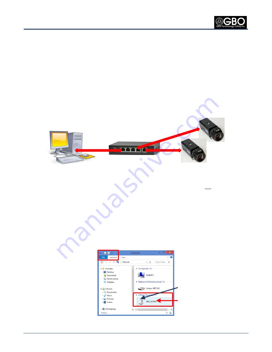
Connect Camera(s) to PC Using Ethernet Cable(s) and POE Switch
Using a standard Ethernet cable, connect the power-over-Ethernet (POE) switch to your PC.
1.
Using standard Ethernet cable(s) connect the POE switch to the camera(s) through the LAN/POE
2.
receptacle(s) located on the back of the camera(s).
Figure 12
PC to POE Switch to Cameras
Step 2.
Power On Camera Through POE
The camera is powered-up through the POE 802.3af-enabled network switch. (If POE support is
not
available, an
external 12V DC power supply is required. See
Step 3, Power On Camera with DC Power Supply
, in
Section 2.1
,
Camera Connected Directly to a Personal Computer
.)
Step 3.
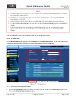
Starting the Web Browser GUI Using UPnP
By default, the GBOT S1080 IP Network Camera has the
User Plug and Play
(UPnP) functionality enabled (see that the
Enable UPNP
checkbox is checked in the
Network and Port Screen
(see Figure 25
)
.
To start the
Web Browser GUI
, browse to the PC’s
Network
dialog box. Under
Other Devices,
double-click
1.
the
GBO_DD:EE:FF
i
con, where
DD:EE:FF
represents the last three bytes of the camera’s media access
control (MAC) address.
Figure 13
UPnP Icon for GBOT IP Network Camera
Ethernet Cable
Ethernet Cables
Camera’s MAC address
UPnP GBO S1080 icon
Networked PC
Cameras
POE Switch


