

www.gateway.com
93
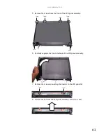
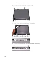
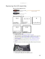
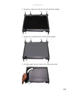
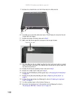
12
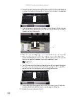
Place the new LCD panel assembly onto the notebook, then replace the hinge screws
removed in
Step 10
.
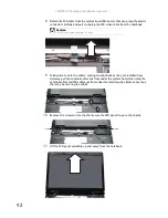
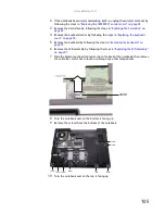
13
Slide the antenna cables through the retaining clips, under the system board, then
into the wireless bay.
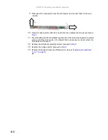
14
Lay the LCD cable along the flat area under the keyboard, then plug it into the
notebook. Run your finger along the cable to re-stick the cable to the notebook.
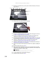
15
Replace any tape that held the antenna wires.
16
Close the LCD panel, turn the notebook over so the bottom is facing up, then replace
the bottom hinge screws removed in
Step 5
.
17
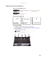
Replace the keyboard by following the steps in
“Replacing the keyboard” on
page 79
.
18
Replace the keyboard cover by following the steps in
“Replacing the keyboard cover”
on page 76
.
19
Turn the notebook over so the bottom is facing up.
20
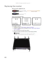
Reconnect the antenna wires to the wireless card by following the steps in
“Replacing the IEEE 802.11 wireless card” on page 63
.
21
Replace the wireless bay cover by following the steps in
“Replacing the IEEE 802.11
wireless card” on page 63
.
Summary of Contents for MG1
Page 1: ... MG1 SERVICEGUIDE ...
Page 11: ...5 System block diagram ...
Page 42: ...CHAPTER 1 System specifications 36 ...
Page 43: ...CHAPTER2 37 System utilities BIOS Setup Utility BIOS flash utility Removing a password lock ...
Page 56: ...CHAPTER 2 System utilities 50 ...
Page 167: ...CHAPTER5 161 Connector locations System board top connectors System board bottom connectors ...
Page 169: ...CHAPTER6 163 FRU Field Replaceable Unit list Introduction Exploded diagram FRU list ...
Page 178: ...CHAPTER 6 FRU Field Replaceable Unit list 172 ...
Page 185: ...APPENDIXC 179 Online support information ...
Page 190: ...Index 184 ...
Page 191: ......
Page 192: ...MAN GODZILLA SVC GDE R1 07 08 ...