


CHAPTER 4: Troubleshooting
144
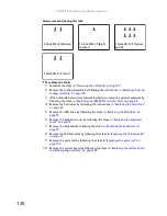
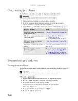
Diagnosing problems
Use the following procedure as a guide for diagnosing notebook problems.
1
Obtain the failing symptoms in as much detail as possible.
2
Verify the symptoms by attempting to re-create the failure by running the
diagnostic test or by repeating the same operation.
3
Use the following table with the verified symptom to determine which page to go to.
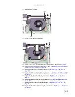
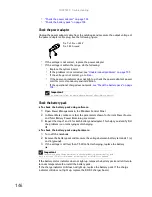
System test procedures
Testing the optical drive
Use the following procedure to isolate a problem in an optical drive controller, driver, or
drive.
To test the optical drive:
1
Boot from the diagnostics diskette and start the diagnostics program.
2
Run the CD-ROM Test and see if the test completes successfully.
3
Follow the instructions in the message window.
If an error occurs, reconnect the connector on the system board.
If the error still remains:
4
Reconnect the external optical drive to a USB jack.
5
Replace the external optical drive.
Important
The diagnostic tests are intended to test only Acer products. Non-Acer products,
prototype cards, or modified options can give false errors and invalid system responses.
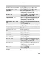
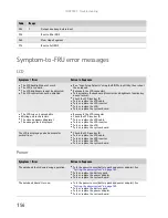
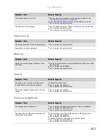
Symptoms (Verified)
Go To
Power failure. (The power indicator does
not go on or stay on.)
“Testing the power system” on page 145
POST does not complete. No beep or error
codes are indicated.
■
“Power-On Self-Test (POST) error
message” on page 147
■
“Undetermined problems” on page 159
POST detects an error and displayed
messages on screen.
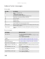
“Index of error messages” on page 148
Other symptoms (LCD display problems or
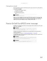
others).
“Power-On Self-Test (POST) error message”
on page 147
Symptoms cannot be re-created
(intermittent problems).
■
Use the customer-reported symptoms
and go to
“Power-On Self-Test (POST)
error message” on page 147
■
“Intermittent problems” on page 159
■
“Undetermined problems” on page 159
Important
Make sure that the CD-ROM does not have any label attached to it. The label can cause
damage to the drive or can cause the drive to fail.
Summary of Contents for MG1
Page 1: ... MG1 SERVICEGUIDE ...
Page 11: ...5 System block diagram ...
Page 42: ...CHAPTER 1 System specifications 36 ...
Page 43: ...CHAPTER2 37 System utilities BIOS Setup Utility BIOS flash utility Removing a password lock ...
Page 56: ...CHAPTER 2 System utilities 50 ...
Page 167: ...CHAPTER5 161 Connector locations System board top connectors System board bottom connectors ...
Page 169: ...CHAPTER6 163 FRU Field Replaceable Unit list Introduction Exploded diagram FRU list ...
Page 178: ...CHAPTER 6 FRU Field Replaceable Unit list 172 ...
Page 185: ...APPENDIXC 179 Online support information ...
Page 190: ...Index 184 ...
Page 191: ......
Page 192: ...MAN GODZILLA SVC GDE R1 07 08 ...