


CHAPTER 3: Replacing notebook components
138
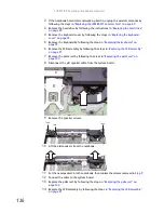
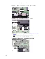
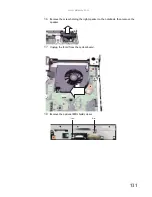
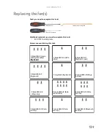
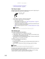
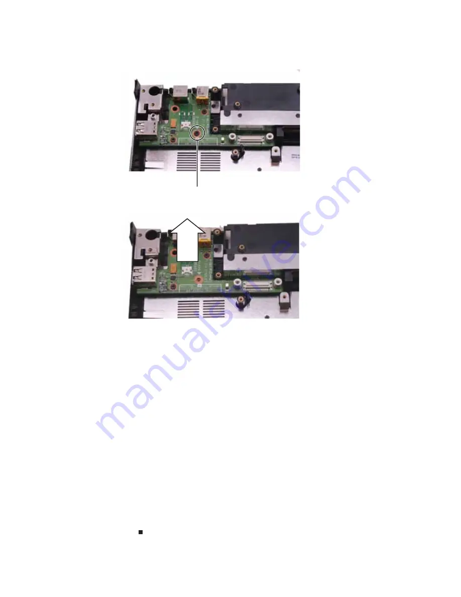
12
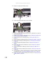
Remove the modem jack/USB board screw.
13
Lift the old modem jack/USB board from the notebook.
14
Set the new modem jack/USB board module into the notebook, then replace the
screw removed in
Step 12
.
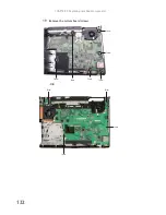
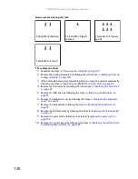
15
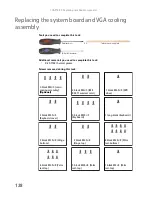
Replace the system board by following the steps in
“Replacing the system board
and VGA cooling assembly” on page 128
.
16
Replace the palm rest by following the steps in
“Replacing the palm rest” on
page 104
.
17
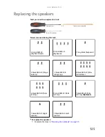
Replace the speaker by following the steps in
“Replacing the speakers” on page 125
.
18
Replace the LCD assembly by following the steps in
“Replacing the LCD assembly”
on page 91
.
19
Replace the keyboard by following the steps in
“Replacing the keyboard” on
page 79
.
20
Replace the keyboard cover by following the steps in
“Replacing the keyboard
cover” on page 76
.
21
Replace the DVD drive by following the steps in
“Replacing the DVD drive” on
page 73
.
22
Replace the hard drive by following the instructions in
“Replacing the hard drive”
on page 69
.
23
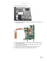
If the notebook has wireless networking built in, reconnect the wireless antennas
by following the steps in
“Replacing the IEEE 802.11 wireless card” on page 63
.
24
Replace the cooling assembly by following the instructions in
“Replacing the main
cooling assembly” on page 58
.
Screw
Summary of Contents for MG1
Page 1: ... MG1 SERVICEGUIDE ...
Page 11: ...5 System block diagram ...
Page 42: ...CHAPTER 1 System specifications 36 ...
Page 43: ...CHAPTER2 37 System utilities BIOS Setup Utility BIOS flash utility Removing a password lock ...
Page 56: ...CHAPTER 2 System utilities 50 ...
Page 167: ...CHAPTER5 161 Connector locations System board top connectors System board bottom connectors ...
Page 169: ...CHAPTER6 163 FRU Field Replaceable Unit list Introduction Exploded diagram FRU list ...
Page 178: ...CHAPTER 6 FRU Field Replaceable Unit list 172 ...
Page 185: ...APPENDIXC 179 Online support information ...
Page 190: ...Index 184 ...
Page 191: ......
Page 192: ...MAN GODZILLA SVC GDE R1 07 08 ...