

CHAPTER 3: Replacing notebook components
62
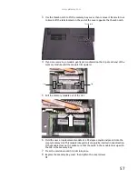
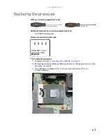
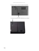
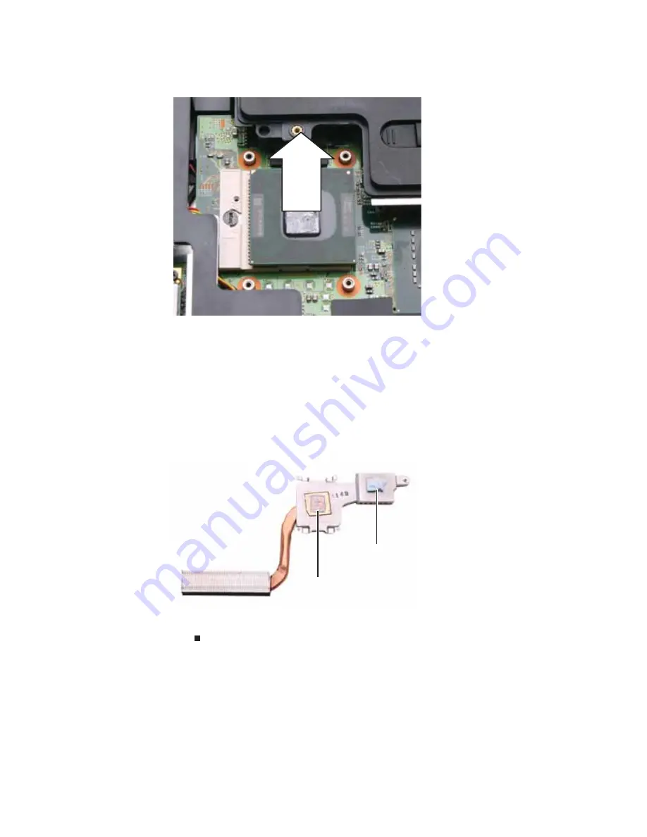
4
Remove the old processor from the system board.
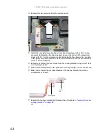
5
Install the new processor onto the system board making sure that Pin 1 on the
processor (indicated by the silk-screened arrow on the corner of the processor)
aligns with Pin 1 on the processor socket (indicated by the absence of a pin hole
in the processor socket), then use a flat-blade screwdriver to turn the processor lock
screw 1/4-turn clockwise.
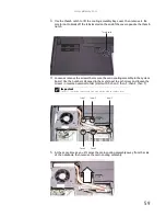
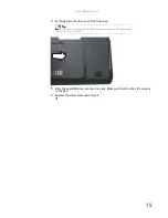
6
Remove any thermal grease residue from the cooling assembly using a soft cloth
and isopropyl alcohol.
7
Place new thermal grease on the processor. Use only enough to cover the CPU die.
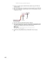
8
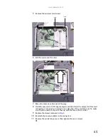
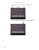
Make sure a thermal pad is placed between the cooling assembly and other
components as shown.
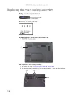
9
Replace the cooling assembly by following the instructions in
“Replacing the main
cooling assembly” on page 58
.
Thermal
pad
Thermal grease
Summary of Contents for MG1
Page 1: ... MG1 SERVICEGUIDE ...
Page 11: ...5 System block diagram ...
Page 42: ...CHAPTER 1 System specifications 36 ...
Page 43: ...CHAPTER2 37 System utilities BIOS Setup Utility BIOS flash utility Removing a password lock ...
Page 56: ...CHAPTER 2 System utilities 50 ...
Page 167: ...CHAPTER5 161 Connector locations System board top connectors System board bottom connectors ...
Page 169: ...CHAPTER6 163 FRU Field Replaceable Unit list Introduction Exploded diagram FRU list ...
Page 178: ...CHAPTER 6 FRU Field Replaceable Unit list 172 ...
Page 185: ...APPENDIXC 179 Online support information ...
Page 190: ...Index 184 ...
Page 191: ......
Page 192: ...MAN GODZILLA SVC GDE R1 07 08 ...