


CHAPTER 4: Troubleshooting
150
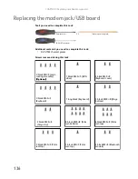
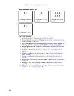
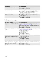
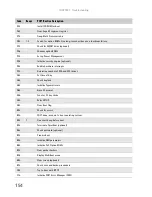
No-beep error messages
Invalid System Configuration Data
■
Test or replace the BIOS ROM.
■
Test or replace the system board.
I/O device IRQ conflict
■
Run “Load Setup Defaults” using the BIOS Setup Utility, then reboot
the notebook.
■
Test or replace the CMOS battery, run the BIOS Setup Utility to
reconfigure system time, then reboot the system.
■
Test or replace the system board.
Operating system not found
■
Run the BIOS Setup Utility and see if fixed disk and drive A: are
properly identified.
■
Test or replace the diskette drive
■
Test or replace the hard disk drive
■
Test or replace the system board
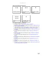
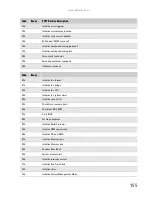
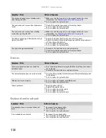
No-beep Error Messages
FRU/Action in Sequence
No beep, power-on indicator turns off and LCD
is blank.
■
Test the power source (battery pack and power adapter).
See
“Testing the power system” on page 145.
■
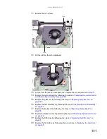
Make sure that every connector is connected tightly and correctly.
■
Reconnect the SO-DIMM.
■
Test or replace the LED board.
■
Test or replace the system board.
No beep, power-on indicator turns on and LCD
is blank.
■
Test the power source (battery pack and power adapter).
See
“Testing the power system” on page 145.
■
Reconnect the LCD connector
■
Check the hard disk drive.
■
Check the LCD inverter ID.
■
Check the LCD cable.
■
Test or replace the LCD inverter.
■
Test or replace the LCD.
■
Test or replace the system board.
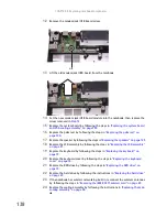
No beep, power-on indicator turns on and LCD
is blank. But you can see POST on an external
CRT.
■
Reconnect the LCD connectors.
■
Check the LCD inverter ID.
■
Check the LCD cable.
■
Test or replace the LCD inverter.
■
Test or replace the LCD.
■
Test or replace the system board.
No beep, power-on indicator turns on and a
blinking cursor shown on LCD during POST.
■
Make sure that every connector is connected tightly and correctly.
■
Test or replace the system board.
No beep during POST but system runs
correctly.
■
Test or replace the speaker.
■
Test or replace the system board.
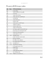
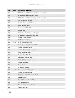
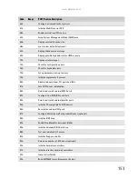
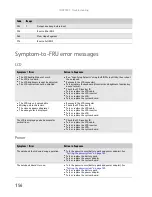
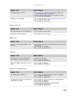
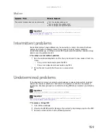
Error Messages
FRU/Action Sequence
Summary of Contents for MG1
Page 1: ... MG1 SERVICEGUIDE ...
Page 11: ...5 System block diagram ...
Page 42: ...CHAPTER 1 System specifications 36 ...
Page 43: ...CHAPTER2 37 System utilities BIOS Setup Utility BIOS flash utility Removing a password lock ...
Page 56: ...CHAPTER 2 System utilities 50 ...
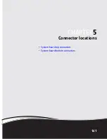
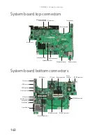
Page 167: ...CHAPTER5 161 Connector locations System board top connectors System board bottom connectors ...
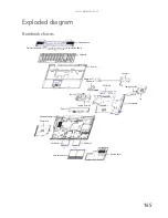
Page 169: ...CHAPTER6 163 FRU Field Replaceable Unit list Introduction Exploded diagram FRU list ...
Page 178: ...CHAPTER 6 FRU Field Replaceable Unit list 172 ...
Page 185: ...APPENDIXC 179 Online support information ...
Page 190: ...Index 184 ...
Page 191: ......
Page 192: ...MAN GODZILLA SVC GDE R1 07 08 ...