


Chapter 3
41
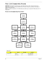
External Module Disassembly Process
NOTE:
The product previews seen in the disassembly procedures may not represent the final product color or
configuration.
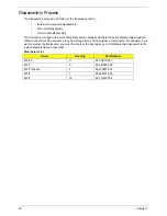
External Modules Disassembly Flowchart
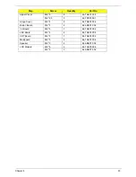
Screw List
Step
Screw
Quantity
Part No.
WLAN
M2*3
1
86.ARE07.002
3G Module
M2*3
1
86.ARE07.002
Disconnect power
and signal cables
from system
Remove
Battery
Turn off system
and peripherals
power
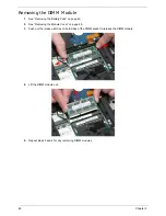
Remove
DIMM
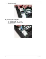
Remove
HDD
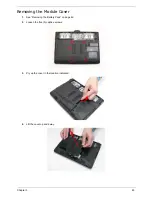
Remove
Lower Cover
Remove
WLAN Board
Remove
Dummy Card
Remove
3G Board
Remove
SIM Card
(Optional)
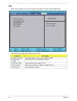
Summary of Contents for EC14T Series
Page 6: ...vi ...
Page 10: ...x Table of Contents ...
Page 13: ...Chapter 1 3 System Block Diagram ...
Page 32: ...22 Chapter 1 ...
Page 48: ...38 Chapter 2 ...
Page 65: ...Chapter 3 55 4 Unlock the FPC 5 Remove the FPC and keyboard ...
Page 67: ...Chapter 3 57 4 Partially open the LCD module 5 Remove the hinge cap ...
Page 83: ...Chapter 3 73 6 Remove the CRT cable ...
Page 96: ...86 Chapter 3 7 Pry up the bezel bottom edge 8 Remove the bezel ...
Page 106: ...96 Chapter 3 4 Remove the hinge ...
Page 110: ...100 Chapter 3 11 Remove both antenna cables from the cover ...
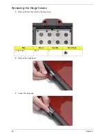
Page 124: ...114 Chapter 3 6 Replace the screw covers 7 Insert the stylus ...
Page 153: ...Chapter 3 143 2 Replace the HDD in the bay 3 Adhere the black tape 4 Replace the HDD FPC ...
Page 158: ...148 Chapter 3 ...
Page 206: ...196 Appendix B ...
Page 208: ...198 ...
Page 211: ...201 ...
Page 212: ...202 ...


