Chapter 1
7
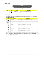
Base View
5
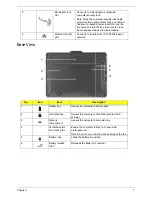
Kensington lock
slot
Connects to a Kensington-compatible
computer security lock.
Note: Wrap the computer security lock cable
around an immovable object such as a table or
handle of a locked drawer. Insert the lock into
the notch and turn the key to secure the lock.
Some keyless models are also available.
6
Ethernet (RJ-45)
port
Connects to an Ethernet 10/100/1000-based
network.
No.
Icon
Item
Description
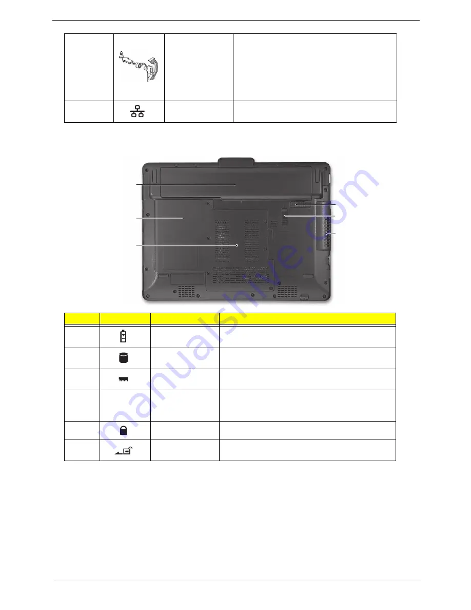
1
Battery bay
Houses the computer's battery pack.
2
Hard disk bay
Houses the computer's hard disk (secured with
screws).
3
Memory
compartment
Houses the computer's main memory.
4
Ventilation slots
and cooling fan
Enable the computer to stay cool, even after
prolonged use.
Note: Do not cover or obstruct the opening of the fan.
5
Battery lock
Locks the battery in position.
6
Battery release
latch
Releases the battery for removal.
1
2
3
4
5
6
Summary of Contents for EC14T Series
Page 6: ...vi ...
Page 10: ...x Table of Contents ...
Page 13: ...Chapter 1 3 System Block Diagram ...
Page 32: ...22 Chapter 1 ...
Page 48: ...38 Chapter 2 ...
Page 65: ...Chapter 3 55 4 Unlock the FPC 5 Remove the FPC and keyboard ...
Page 67: ...Chapter 3 57 4 Partially open the LCD module 5 Remove the hinge cap ...
Page 83: ...Chapter 3 73 6 Remove the CRT cable ...
Page 96: ...86 Chapter 3 7 Pry up the bezel bottom edge 8 Remove the bezel ...
Page 106: ...96 Chapter 3 4 Remove the hinge ...
Page 110: ...100 Chapter 3 11 Remove both antenna cables from the cover ...
Page 124: ...114 Chapter 3 6 Replace the screw covers 7 Insert the stylus ...
Page 153: ...Chapter 3 143 2 Replace the HDD in the bay 3 Adhere the black tape 4 Replace the HDD FPC ...
Page 158: ...148 Chapter 3 ...
Page 206: ...196 Appendix B ...
Page 208: ...198 ...
Page 211: ...201 ...
Page 212: ...202 ...


