© ANITA
MP03200
EN_180810
28
19.
Operation of pedals:
a)
Function of pedals can be defined according to requirement of operator by parameters 8,9
and 10.
b)
Machine is standardly
supplied with 2
-
piece presser frame and 3 pedals (see chart 1). If
middle pedal is not used, it is possible to use the same setting which is used for machine with
2 pedals (see chart 2).
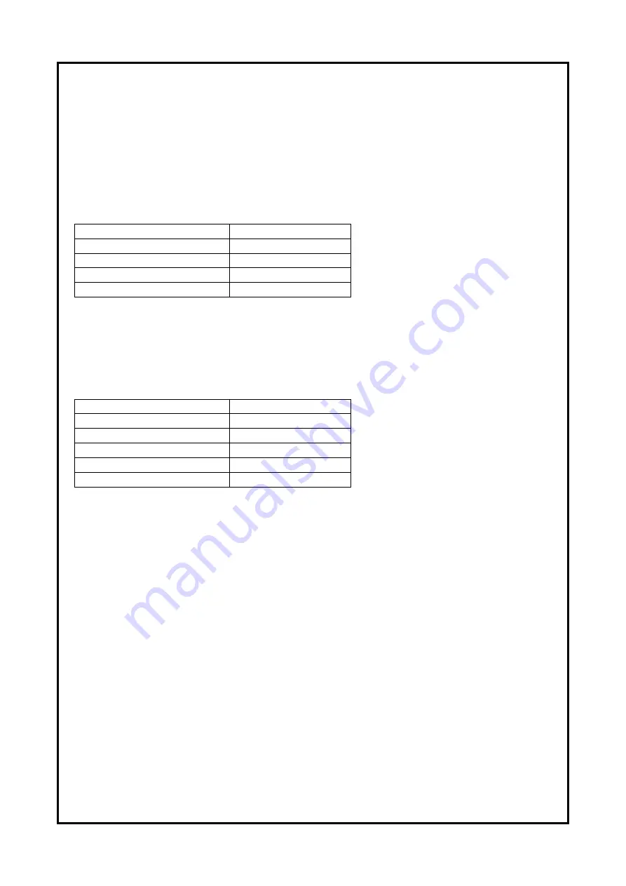
Chart
1:
Setting for operation with 3 pedals:
Parameter
Value
6
Feed plate type
1
Two feed plate
8
Signal of pedal 1 (left)
1
Start sewing
9 Signal of pedal 2 (middle)
2 Left feed plate
10 Sign
al of
pedal
3 (right)
3 Right feed plate
c)
In case of use of customized fixing frames (pallets) it is possible to use 3 pedals accordingly:
right pedal is used for locking and unlocking of the pallet, middle pedal is used for pressing
down the upper frame and left pedal is used for start of the sewing of selected pattern. This
setting is described in chart 1.
Chart 2:
Sett
ing for operation with 2 pedals
:
Parameter
Value
6
Feed plate type
2 Upper and
botto
m
8 Signal of pedal 1 (left)
1 Start
sewing
9 Sign
al of
ped
a
l 2 (middle)
0
Disable
10 Sign
al of
ped
a
l 3 (right)
4 Both feed plate
5 Operation of presser frame
2 In operation
d)
In case of use of customized fixing frames (pallets) it is possible to use option with 2 pedals
–
setting described in chart 2. Parameter 6 is set for the value „Upper and bottom“. Right pedal
is used for pressing up and down the upper frame and left pedal is used for start of the
sewing of selected pattern.
Operation of presser frames is additionally is defined by parameters 5,
6 and 7.
The above setting is only standard setting which user can change according to his requirements.
www.garudan.cz
Summary of Contents for GPS/X-3525 Series
Page 5: ...ANITA MP03200EN_180810 5 2 DESCRIPTION Fig 1 w w w g a r u d a n c z...
Page 32: ......
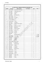
Page 36: ...ANITA MP03200EN_180822 4 A FRAME AND MACHINE BODY PARTS w w w g a r u d a n c z...
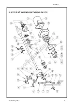
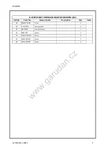
Page 38: ...ANITA MP03200EN_180822 6 B UPPER SHAFT AND MAIN SHAFT MECHANISM 1 2 w w w g a r u d a n c z...
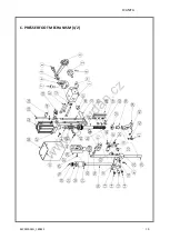
Page 42: ...ANITA MP03200EN_180822 10 C PRESSER FOOT MECHANISM 1 2 w w w g a r u d a n c z...
Page 44: ...ANITA MP03200EN_180822 12 C PRESSER FOOT MECHANISM 2 2 w w w g a r u d a n c z...
Page 46: ...ANITA MP03200EN_180822 14 D LOWER SHAFT AND SHUTTLE MECHANISM 1 2 w w w g a r u d a n c z...
Page 48: ...ANITA MP03200EN_180822 16 D LOWER SHAFT AND SHUTTLE MECHANISM 2 2 w w w g a r u d a n c z...
Page 50: ...ANITA MP03200EN_180822 18 E THREAD TRIMMING MECHANISM 1 2 w w w g a r u d a n c z...
Page 54: ...ANITA MP03200EN_180822 22 G X MOVING MECHANISM 1 2 w w w g a r u d a n c z...
Page 56: ...ANITA MP03200EN_180822 24 G X MOVING MECHANISM 2 2 w w w g a r u d a n c z...
Page 58: ...ANITA MP03200EN_180822 26 I FEED FRAME MECHANISM 1 2 w w w g a r u d a n c z...
Page 60: ...ANITA MP03200EN_180822 28 I FEED FRAME MECHANISM 2 2 w w w g a r u d a n c z...
Page 62: ...ANITA MP03200EN_180822 30 I2 FEED FRAME FOR CUSTOMER DESIGN w w w g a r u d a n c z...
Page 64: ...ANITA MP03200EN_180822 32 J THREAD TENSION MECHANISM w w w g a r u d a n c z...
Page 66: ...ANITA MP03200EN_180822 34 K BOBBIN WINDER AND HAND PULLEY w w w g a r u d a n c z...
Page 68: ...ANITA MP03200EN_180822 36 L STAND AND TABLE w w w g a r u d a n c z...
Page 70: ...ANITA MP03200EN_180822 38 M LUBRICATION PARTS w w w g a r u d a n c z...
Page 72: ...ANITA MP03200EN_180822 40 N AIR CONTROL PARTS w w w g a r u d a n c z...
Page 74: ...ANITA MP03200EN_180822 42 Q OPERATION UNIT AND THREAD STAND w w w g a r u d a n c z...
Page 76: ...ANITA MP03200EN_180822 44 R CONTROL BOX w w w g a r u d a n c z...
Page 78: ...ANITA MP03200EN_180822 46 S OPTION w w w g a r u d a n c z...


