© ANITA
MP03200
EN_180810
18
c)
Lever 4, (Fig.
22), is driven by the eccentric and it is joined with the adjusting pin and nut on
the lever with the groove (5) in the part located outside the machine. If the pin is in the
upper part of
the groove, the presser foot movement is set to minimum. If the pin is in the
lower part of the groove, the presser foot movement is set to maximum.
d)
Movement is transmitted on the lever mechanism through the lever (10) with clamping joint
and screw,
F
ig.21. Distance of presser foot (17) above the needle plate (sewn material) is set
by the screw (6) which leans against the pin (12) of the lever mechanism, see
F
ig. 21.
e)
Lift of the presser bar during exchange of the material, when the machine is not in operation,
is performed by pneumatic cylinder (16), see
F
ig. 21.
f)
Pressure of the presser foot is adjusted by pressing the spring (13). This spring can be
adjusted after losing nut (14) by turning the screw (15).
Summary: presser foot (17) should be moving with the delay defined by the value of approximately
5
mm of the needle trajectory during the movement from the lower reversal point. When the sewn
material is moving and the needle is above the material, the presser foot must not be in contact with
the material.
5.
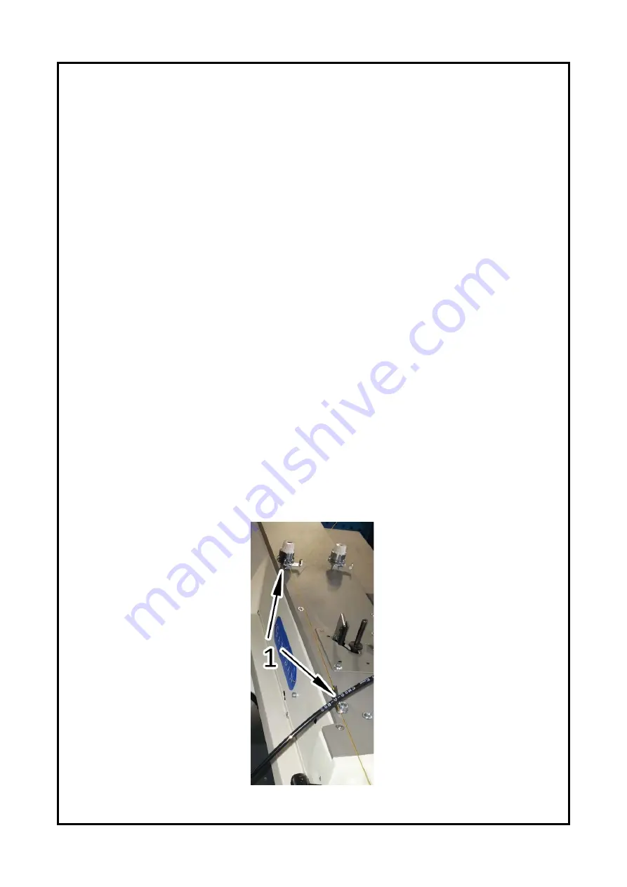
Thread of upper thread:
Lead the thread from thread stand to guides (1) on the head of the machine,
F
ig.23. After that thread
through silicon oil bottle for lubrication (
F
ig.6). The bottle can also be placed between the guides (1).
After that lead the thread through tensioner (3), guide (4), tensioner (5) and spring (6), see
F
ig. 24.
Then lead the thread through guide (8), thread puller (9), thread holder (10), guide (11) and guide
(12) to the needle where the thread is inserted from
the operator side in the direction of the arrow
(13) (see
F
ig. 25).
Fig. 23
www.garudan.cz
Summary of Contents for GPS/X-3525 Series
Page 5: ...ANITA MP03200EN_180810 5 2 DESCRIPTION Fig 1 w w w g a r u d a n c z...
Page 32: ......
Page 36: ...ANITA MP03200EN_180822 4 A FRAME AND MACHINE BODY PARTS w w w g a r u d a n c z...
Page 38: ...ANITA MP03200EN_180822 6 B UPPER SHAFT AND MAIN SHAFT MECHANISM 1 2 w w w g a r u d a n c z...
Page 42: ...ANITA MP03200EN_180822 10 C PRESSER FOOT MECHANISM 1 2 w w w g a r u d a n c z...
Page 44: ...ANITA MP03200EN_180822 12 C PRESSER FOOT MECHANISM 2 2 w w w g a r u d a n c z...
Page 46: ...ANITA MP03200EN_180822 14 D LOWER SHAFT AND SHUTTLE MECHANISM 1 2 w w w g a r u d a n c z...
Page 48: ...ANITA MP03200EN_180822 16 D LOWER SHAFT AND SHUTTLE MECHANISM 2 2 w w w g a r u d a n c z...
Page 50: ...ANITA MP03200EN_180822 18 E THREAD TRIMMING MECHANISM 1 2 w w w g a r u d a n c z...
Page 54: ...ANITA MP03200EN_180822 22 G X MOVING MECHANISM 1 2 w w w g a r u d a n c z...
Page 56: ...ANITA MP03200EN_180822 24 G X MOVING MECHANISM 2 2 w w w g a r u d a n c z...
Page 58: ...ANITA MP03200EN_180822 26 I FEED FRAME MECHANISM 1 2 w w w g a r u d a n c z...
Page 60: ...ANITA MP03200EN_180822 28 I FEED FRAME MECHANISM 2 2 w w w g a r u d a n c z...
Page 62: ...ANITA MP03200EN_180822 30 I2 FEED FRAME FOR CUSTOMER DESIGN w w w g a r u d a n c z...
Page 64: ...ANITA MP03200EN_180822 32 J THREAD TENSION MECHANISM w w w g a r u d a n c z...
Page 66: ...ANITA MP03200EN_180822 34 K BOBBIN WINDER AND HAND PULLEY w w w g a r u d a n c z...
Page 68: ...ANITA MP03200EN_180822 36 L STAND AND TABLE w w w g a r u d a n c z...
Page 70: ...ANITA MP03200EN_180822 38 M LUBRICATION PARTS w w w g a r u d a n c z...
Page 72: ...ANITA MP03200EN_180822 40 N AIR CONTROL PARTS w w w g a r u d a n c z...
Page 74: ...ANITA MP03200EN_180822 42 Q OPERATION UNIT AND THREAD STAND w w w g a r u d a n c z...
Page 76: ...ANITA MP03200EN_180822 44 R CONTROL BOX w w w g a r u d a n c z...
Page 78: ...ANITA MP03200EN_180822 46 S OPTION w w w g a r u d a n c z...


