background image

Part #4519655 Rev.2 (Jan 27/15)

Page 7

INSTALLATION continued

Leg Installation

G24 Series

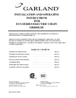
Your new appliance has been supplied with four 4”(102mm) 
adjustable legs. These legs are threaded into holes on the 
bottom. Once the legs are installed turn the leveling foot at 
the bottom of the leg. 

UNDERSIDE OF UNIT

4" [102mm]

ADJUSTABLE LEG

LEG INSTALLATION

LEVELING FOOT

Level the appliance by adjustment of leveling bolts or legs. 
Use a spirit level and check for level four ways; across front 
and back, then down left and right edges. Level any adjacent 
units to the fi rst. A griddle may not rest evenly on the 
appliance body if it is not properly leveled.

Installation of Banking Plates

G24 Series

All units may be installed independently or banked with 
other G24 or E24 Series equipment. To ensure a matching 
and permanent fi t between units, a front banking plate is 
supplied with each unit. If 2” (51 mm) legs are supplied with 
nit, discard leveling bolts and replace with 2” (51 mm) legs.

1.  Level each unit by adjusting leveling bolts or legs. Use a 

spirit level and level unit four ways; across front and back 
and down left and right edges. Level all other units to the 
fi rst unit, securing each unit to the adjacent unit.


NOTE:  Griddles may not rest evenly on the unit body, if 
units are not leveled. 

2.  Remove upper front panel (if not already removed) by 

removing the thumb screws on each side of the panel.

3.  Place the banking plate in position, over the two bolts 

located in the main sides below the panel mounting 
brackets.


NOTE:  Install recessed (stepped) centre portion of 
banking plate tight to the main sides of the units being 
banked. Secure in place with two hex nuts supplied.

4.  Replace and secure upper front panels.

5.  Connect gas supply line using either rear or bottom inlet, 

as desired. A readily accessible approved type of hand 
valve should be installed on each supply line. Test For 
Leaks.

Installing Equipment on Counter Stands

CS24 Series Stands

1.  Assemble and level counter stand as illustrated in the 

instructions found in the counter stand carton.

2.  Remove and discard leveling bolts on unit to be installed 

on the counter stand.

3.  Remove only the side, front and rear sheet metal screws 

in the main bottom of units to be placed on the outer 
sides of the stand.

4.  Place units in desired position on the counter stand, 

securing the fi rst unit with sheet metal screws removed in 
paragraph 3, by inserting the sheet metal screws through 
the 9/32 inch (7 mm) diameter holes in stand, into the 
holes from which the sheet metal screws were removed.

5.  Connect banking plates as described in G24 Series 

Installation Of Banking Plates.

6.  Secure last unit to the counter stand with sheet metal 

screws removed in paragraph 3. Insert sheet metal screws 
through the 9/32 inch (7 mm) diameter holes in stand, 
into the holes from which the sheet metal screws were 
removed.

Summary of Contents for G24 SERIES

Page 1: ...EQUIPMENT G20 SERIES STOCK POT RANGES Installation Operation and Maintenance Manual This manual is updated as new information and models are released Visit our website for the latest manual Model G20 SP stock pot not included ...

Page 2: ...hat has its serial number defaced obliterated or removed or which has been modified or repaired using unauthorized parts or by unauthorized service agents For a list of authorized service agents please refer to the Garland web site at http www garland group com The information contained herein including design and parts specifications may be superseded and is subject to change without notice FOR Y...

Page 3: ...Gas Connections 6 Inlet Manifold Size 6 Leg Installation 7 Installation of Banking Plates 7 Installing Equipment on Counter Stands 7 OPERARATION 8 Hot Plate Model G24 15H 8 G24 Griddles 8 G20 SP and G20 SPH Stock Pot Range 8 Lighting Standing Pilots All Models 9 FLAME SIZE CHART ALL MODELS 10 CLEANING AND MAINTENANCE 10 Exterior 10 Top Sections 11 Griddle Top 11 Open Top 11 Stock Pot Ranges 11 ...

Page 4: ...re Required Combustible Wall Clearances In mm Supply Operating Pressures Manifold Operating Pressures Sides Back Base Natural Propane Natural Propane 6 152 6 152 Non combustible 7 WC 17 5 mbar 11 WC 27 5mbar 4 WC 10 mbar 10 WC 24mbar NOTE Installation clearance reductions are applicable only where local codes permit Note For use with Natural L P Gas only Ratings shown are for natural gas installat...

Page 5: ...amage incurred in shipping After carefully uncrating check for concealed damage Report any damage immediately to your carrier 2 Carefully remove unit from carton or crate Burner tie wires and other packing material should be removed from units On stainless steel and brushed units the protective material covering the stainless steel should be removed immediately after the unit is installed 3 Remove...

Page 6: ...ne gas unless specified differently on the rating plate INSTALLATION continued 3 Have a qualified gas technician check the gas pressure to make certain that existing gas facilities meter piping etc will deliver the BTU s of gas required at the unit with no more than 1 2 water column pressure drop When checking pressure be certain that all the equipment on same gas line is turned to the ON position...

Page 7: ...dy removed by removing the thumb screws on each side of the panel 3 Place the banking plate in position over the two bolts located in the main sides below the panel mounting brackets NOTE Install recessed stepped centre portion of banking plate tight to the main sides of the units being banked Secure in place with two hex nuts supplied 4 Replace and secure upper front panels 5 Connect gas supply l...

Page 8: ...st to obtain the low cooking temperature desired maintaining a stable flame covering the entire burner minimum 3 16 inch 5 mm long flame 5 Replace dial and turn to OFF position Calibration Instructions 1 Use a test instrument with a special disc type thermocouple or a reliable surface type pyrometer Note a drop of oil on the face of the disc will provide better contact with the plate 2 Set all gri...

Page 9: ...he gas appliance has been installed by a licensed gas trades person all connections pilot lights and controls have been inspected for proper operation All gas appliances that use standing pilot systems are generally assumed to be operating with the pilot on continuously The units should not be restarted except in the event of a gas service interruption to the facility If a pilot flame does go out ...

Page 10: ...aler regarding service problems or replacement parts be sure to refer to the particular unit by the correct model number including prefix and suffix letters and numbers and the serial or code number The rating plate affixed to the unit contains this information Regular Maintenance Ensures Peak Performance Exterior Black baked enamel offered only on older models Allow the equipment to cool after us...

Page 11: ...dle Operating Suggestions 1 Avoid overheating the griddle as this causes sticking and grease carbonization resulting in a hard to clean surface 2 Do not hit spatula on griddle plate as this will nick the surface 3 Clean the grease tray often to eliminate spillovers CLEANING AND MAINTENANCE continued Open Top Porcelain Tops Grates Top grates should be washed daily with a hot detergent or soap solut...

Page 12: ...tinuing product improvement may necessitate change of specifications without notice Every new piece of Manitowoc Foodservice equipment comes with KitchenCare and you choose the level of service that meets your operational needs from one restaurant to multiple locations StarCare Warranty lifetime service certified OEM parts global parts inventory performance audited ExtraCare CareCode 24 7 Support ...

Page 13: ...inuing product improvement may necessitate change of specifi cations without notice Every new piece of Manitowoc Foodservice equipment comes with KitchenCare and you choose the level of service that meets your operational needs from one restaurant to multiple locations StarCare Warranty lifetime service certifi ed OEM parts global parts inventory performance audited ExtraCare CareCode 24 7 Support...

Page 14: ...r les débordements Feux Overts Surface De Cuisson En Porcelaine La surface de cuisson devrait être nettoyée quotidiennement avec un détergent chaud ou une solution savonneuse et asséchée complètement Lèchefrites Devraient être vidées et lavées quotidiennement Suggestions Au Mode D emploi 1 Evitez l usage de chaudrons demesurés 2 Evitez les débordements 3 Des chaudrons couvents bouilleront plus rap...

Page 15: ...éro de série ou de code La plaque signalétique fi xée à l appareil contient ces renseignements Un entretien régulier assure des performances optimales Extérieur Émail Cuit Noir Laissez refroidir l appareil et nettoyez les parois avec une solution savonneuse ou un détergent doux Essuyez bien NE PAS EMPLOYER D ABRASIFS Fini Chrome Ou Nickel Même procédure que ci haut mentionné NE PAS EMPLOYER D ABRA...

Page 16: ...ent être eff ectués au régulateur de pression UTILISATION suite Allumage Des Veilleuses Permanentes Ces appareils ne sont pas conçus pour être débranchés de la conduite de gaz et être rebranchés de façon régulière On ne devra pas utiliser de conduites à raccord rapide Une fois que l appareil à gaz a été installé par un professionnel licencié le fonctionnement correct des branchements veilleuses et...

Page 17: ...eilleuses doivent avoir une longueur de 3 4 po 19 mm Réglage Des Robinets Hi Lo Les grils dotés de robinets Hi Lo ont besoin d un réglage de fl amme basse Pour eff ectuer ce réglage procéder comme suit 1 Le brûleur doit être froid 2 S assurer que les veilleuses sont allumées et réglées 3 Tourner le cadran en position LO et retirer le cadran 4 Avec un tournevis tourner la petite vis de réglage à l ...

Page 18: ...niveau les autres appareils par rapport au premier appareil en fi xant chaque appareil à l appareil voisin NOTA Les grils peuvent ne pas reposer correctement si les appareils ne sont pas de niveau 2 Déposer le panneau avant supérieur s il n a pas été déjà déposé en retirant les vis à ailettes de chaque côté du panneau 3 Mettre en place la plaque d union sur les deux boulons situés sur les deux côt...

Page 19: ... sur la plaque signalétique INSTALLATION suite 3 Faire vérifi er la pression du gaz par un technicien qualifi é afi n de s assurer que les installations de gaz existantes compteur tuyauteries etc fourniront les BTU dont l appareil a besoin avec une chute de pression ne dépassant pas po de colonne d eau Pour vérifi er la pression s assurer que tout l équipement branché sur la conduite de gaz est en...

Page 20: ...dant l expédition Après un déballage soigneux vérifi er la présence de dommages cachés Signaler immédiatement tout dommage au transporteur 2 Retirer avec précaution l appareil du carton ou de la caisse Retirer de l appareil les fi ls d attache des brûleurs et le matériel d emballage Sur les appareils en acier inoxydable et brossé le matériau de protection couvrant l acier inoxydable doit être reti...

Page 21: ...Arrière Base Gaz Naturel Propane Gaz Naturel Propane 6 152 6 152 Incombustible 7 po CE 17 5 mbars 11 po CE 27 5 mbars 4 po CE 10 mbars 10 po CE 4 mbars NOTA Les réductions de dégagement d installation ne sont applicables que lorsque les codes locaux les autorisent Nota Utilisation avec du gaz naturel et du GPL seulement Les débits calorifi ques s appliquent à des installations de gaz naturel infér...

Page 22: ...sion Du Collecteur D entrée 6 Installation Des Pieds 7 Installation Des Plaques D union 7 Installation De L équipement Sur Les Socles De Plan De Travail 7 UTILISATION 8 Plaque Chauff ante Modèle G24 15H 8 Grils G24 8 Cuisinière À Marmite G20 SP et G20 SPH 8 Allumage Des Veilleuses Permanentes 9 TABLEAU DES TAILLES DE FLAMME TOUS LES MODÈLES 10 ENTRETIEN ET NETTOYAGE 10 Extérieur 10 Surfaces De Cui...

Page 23: ...orte quel produit dont le numéro de série aurait été mutilé oblitéré ou supprimé ou qui aurait été modifi é ou réparé avec des pièces non autorisées ou par des agents d entretien non autorisés Pour obtenir la liste des agents de service autorisés consulter le site web de Garland à http www garland group com Les renseignements contenus dans le présent document y compris la conception et les spécifi...

Page 24: ...OMPTOIR À GAZ SÉRIE G24 ET CUISINIÈRES À MARMITE SÉRIE G20 Instructions D installation et D utilisation This manual is updated as new information and models are released Visit our website for the latest manual Model G20 SP stock pot not included ...

Reviews: