


13–10–612 Page 37
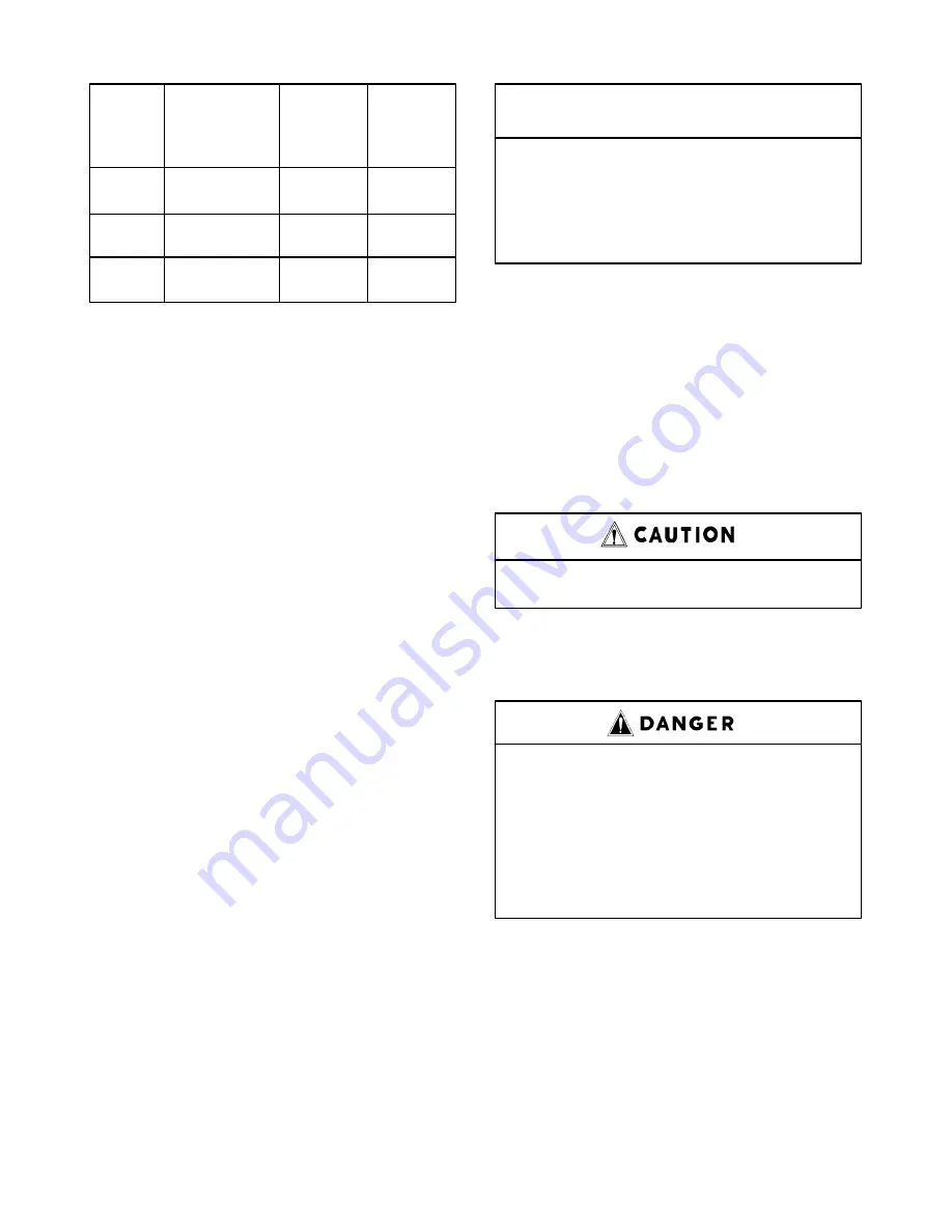
Approx.
Oil
Qty. – Top
System
Reservoir
of ADD to
Capacity
Capacity**
Centerline
Size
(Initial Fill)
(Refill)
of RUN
200 HP
Air Cld* – 57
50
11
Water Cld – 53
250 HP
Air Cld* – 57
50
11
Water Cld – 53
300 HP
Air Cld* – 80
70
12
Water Cld – 75
*
System capacity shown is for the initial fill of the compressor
unit and oil cooler module ONLY – remotely mounted oil cool-
ers will require additional oil to fill the piping between the com-
pressor unit and the oil cooler.
**
The oil reservoir refill quantity shown is measured at the cent-
erline of the oil level gauge RUN range or approximately 3.5
inches below the centerline of the oil reservoir.
FIGURE 5–2 – OIL SYSTEM CAPACITIES
(APPROXIMATE) – U.S. GALLONS
OIL LEVEL GAUGE (FIGURE 1–3, page 2) indicate
the amount of oil in the oil reservoir. When the unit is
stopped, the oil level will be higher in the RUN range
than when operating on load. When the unit is operat-
ing, the oil level should be near the center of the RUN
range. In normal operation, the oil level will fluctuate
slightly as the compressor loads and unloads. Add oil
only when the oil level gauge indicates in the ADD OIL
range when the compressor is loaded. Drain oil only
when the oil level gauge indicates EXCESS OIL when
the compressor is loaded.
MOISTURE IN THE OIL SYSTEM – In normal humid-
ity and with normal operating temperatures and pres-
sures, the thermal mixing valve controls the oil temper-
ature and prevents moisture contamination of the oil.
Unusual cooling of the oil reservoir, short loaded cycle
in high humidity, malfunctions of the thermal valve or
cooling water system may result in moisture in the oil
system which is detrimental to compressor lubrication
and could cause oil carryover. If moisture is observed
in the oil reservoir, drain the moisture and correct the
condition causing the accumulation. See ”Compressor
Oil System Check” and ”Thermal Control (Thermostat-
ic Mixing) Valve” in this section.
OIL CHANGE INTERVAL – Recommended oil change
intervals are based on oil temperature. FIGURE 5–3
shows how the Auto Sentry ES Controller figures the
oil change interval at various temperatures.
Discharge
AEON 4000
AEON 9000 SP
Temperature
Change Interval
Change Interval
Up to 180
_
F
6000 hrs.
8000 hrs.
180 to 190
_
F
4500 hrs.
6000 hrs.
190 to 200
_
F
3000 hrs.
4000 hrs.
200 +
1500 hrs.
2000 hrs.
FIGURE 5–3 – OIL CHANGE INTERVAL
When operating conditions are severe (very dusty, high
humidity, etc.) it will be necessary to change the oil
more frequently. Operating conditions and the appear-
ance of the drained oil must be surveyed and the oil
change intervals planned accordingly by the user.
Gardner Denver offers a free oil analysis program with
the AEON lubricants and we recommend a sample be
sent in at 1000 hours on a new unit.
Change the oil filter every 1000 hours.
DRAINING AND CLEANING OIL SYSTEM –
Air/oil under pressure will cause
severe personal injury or death. Shut
down compressor, relieve system of
all pressure, disconnect, tag and
lockout power supply to the starter
before removing valves, caps, plugs,
fittings, bolts, and filters.
Always drain the complete system. Draining when the
oil is hot will help to prevent varnish deposits and carry
away impurities. To drain the system, use one of the
following methods:
1.
If the unit is not elevated high enough to use the
oil reservoir drain line to drain oil, a small hand,
electric or air operated pump should be used to
drain reservoir through the oil filler opening or from
the drain valve. Remove the oil cooler drain plug.
Summary of Contents for ELECTRA-SAVER EAU PD - 200 HP
Page 13: ...13 10 612 Page 3 FIGURE 1 4 STARTER BOX FIGURE 1 5 PACKAGE CONTROLLER AND STARTERS...
Page 16: ...13 10 612 Page 6 DECALS 206EAQ077 212EAQ077 218EAQ077 211EAQ077 207EAQ077...
Page 17: ...13 10 612 Page 7 DECALS 216EAQ077 217EAQ077 222EAQ077 221EAQ077 208EAQ077...
Page 40: ...13 10 612 Page 30 FIGURE 4 8 CONTROL SCHEMATIC COMPRESSOR AT FULL LOAD 214ECM797 Ref Drawing...
Page 42: ...13 10 612 Page 32 FIGURE 4 10 WIRING DIAGRAM 212EAP546 Ref Drawing...
Page 43: ...13 10 612 Page 33 FIGURE 4 11 AUTO SENTRY ES CONTROLLER DISPLAY...
Page 45: ...13 10 612 Page 35 FIGURE 5 1 FLOW DIAGRAM AIR OIL SYSTEM 215EAU797 Ref Drawing...
Page 65: ......