background image

13–8–612    Page 27

Changing the oil will be of little benefit if done in a care-
less manner.

COMPRESSOR OIL FILTER (FIGURE 1–2, Section
1, page 2) – This replaceable element filter is a vital part
in maintaining a trouble–free compressor, since it re-
moves dirt and abrasives from the circulated oil.  The
filter is equipped with a relief valve that opens in the
event the element becomes dirty enough to block the
flow of oil.  Use only the replacement element shown
on the filter tag or refer to the parts list for the part num-
ber.

Use the following procedure to replace the filter ele-
ment.  Do  not disturb the piping.

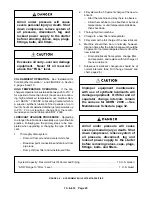
Improper oil filter maintenance will
cause damage to equipment.  Replace
filter element every 1000 hours of op-
eration. More frequent replacement
could be required depending on oper-
ating conditions.  A filter element left
in service too long may damage
equipment.

1.

Stop unit and be sure no air pressure is in the oil
reservoir.

2.

Remove the spin–on element.

3.

Clean the gasket face of the filter body.

4.

Coat the new element gasket with clean lubricant
used in the unit.

5.

Screw new element on filter body and tighten by
hand. DO NOT OVERTIGHTEN ELEMENT.

6.

Run the unit and check for leaks.

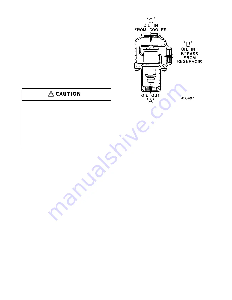
THERMAL CONTROL (THERMOSTATIC MIXING)
VALVE
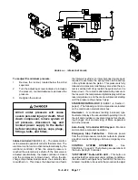
 (FIGURE 5–4) is installed in system as shown
in FIGURE 4–1, Section 4, page 15.  This valve is used
to control temperature of the oil both air–cooled radia-
tor and water–cooled heat exchanger type oil cooler
systems. On start–up with unit cold, element is open to
bypass, allowing oil to pass directly from the reservoir
to compressor during warm–up.  As oil warms, element
gradually closes to the bypass allowing more of the oil
from the cooler to mix with oil from the bypass.

After the unit is warmed up, the mixing valve maintains
oil injection temperature into the compressor at a mini-
mum of 170

_

 F.  This system provides  proper  com-

FIGURE 5–4  –  THERMOSTATIC MIXING VALVE

pressor  warm–up and prevents moisture contamina-
tion of the oil.

To check the element, heat in oil – it should be fully ex-
tended at 170

_

 F.  If the unit shuts down due to high air

discharge temperature, the cause may be that the ele-
ment is stuck open to the bypass, in which case bypass
lines (FIGURE 4–1, Section 4, page 15) will be hot to
touch and lines out of mixing valve much cooler.  When
flushing the oil system, remove the mixing valve and
clean all parts thoroughly.

OIL RESERVOIR – The oil reservoir–separator, lo-
cated in the compressor housing, combines multiple
functions into one vessel. The lower half is the oil reser-
voir, providing oil storage capacity for the system and
the top portion, a primary oil separation means. The
reservoir also provides limited air storage for control
and gauge actuation.

COMPRESSOR OIL SEPARATOR – The compressor
oil separator located on top of the filter housing,
screwed onto a fitting, features a renewable spin–on
type separator element and provides the final removal
of oil from the air flow.

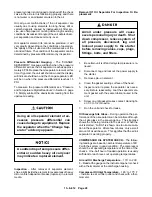
Oil carry–over through the service lines may be caused
by a faulty oil separator, overfilling of the oil reservoir,
oil that foams, oil return line malfunction, or water con-
densate in the oil.  If oil carryover occurs, inspect the
separator only after it is determined that the oil level is
not too high, the oil is not foaming excessively, the oil
return tube from the bottom of the separator to the com-

Summary of Contents for EBB BB-7.5 HP

Page 1: ...ASE MOUNTED with INTEGRATED DRYER and TANK MOUNTED COMPRESSORS MODELS EBB_BB 7 5 HP ES 7 5 EBB_CB 10 HP ES 10 0 EBB_DB 15 HP ESS 15 0 PARTS LIST OPERATING AND SERVICE MANUAL 13 8 612 2nd Edition March...

Page 2: ...er Denver is committed to supplying you with the highest quality factory remanufactured air ends that are guaranteed to save you time aggravation and money Immediately Available Repair downtime costs...

Page 3: ...resence of a hazard which will cause severe personal injury death or substantial property damage if the warning is ignored Warning is used to indicate the presence of a hazard which can cause severe p...

Page 4: ...Index v thru vii List of Illustrations viii Model EBB 7 5 10 15 HP Electra Screwr Compressors Matrix Menu ix Section 1 General Information 1 Section 2 Installation 8 Section 3 Starting Operating Proc...

Page 5: ...essor lubricants specifically formulated for use in Gard ner Denver compressors 4 Repair and maintenance kits designed with the necessary parts to simplify servicing your com pressor Authorized distri...

Page 6: ...Compressor System Air Flow 1 CONSTANT RUN Button with LED 18 Control Piping 10 Control System Operation 17 AUTO LAG Button with LED 18 AUTO LEAD Button with LED 18 Change Air Filter LED 18 Change Sep...

Page 7: ...10 Motor Grease Recommendations 12 Motor Group Fan Motors 56 Main Motor 56 Motor Lubrication 11 Motor Overload LED 18 Motor Protection Devices 15 Motor Regreasing Interval 12 Mounting Group 45 Oil Ch...

Page 8: ...ant 24 Refrigeration Components 71 Regreasing Interval Electric Motor 12 Relief Valve 16 Remanufactured Air Ends i Repair Parts 59 Ordering Instructions iv Reservoir Oil 27 Safety Precautions 4 5 Seal...

Page 9: ...oints for Auto Sentry S Controller PSIG 21 Figure 4 7 Auto Sentry S Solid State Control Touch Pad 22 Figure 4 8 Wiring Diagram 23 Figure 5 1 Oil Fill 24 Figure 5 2 Approximate Oil System Capacities 25...

Page 10: ...5 PSI J 15 0 HP 175 PSI E 10 0 HP 125 PSI K 10 0 HP 100 PSI F 10 0 HP 150 PSI L 15 0 HP 100 PSI COLUMN 8 COOLING FAN MOTOR Per Voltage H P A 200V 15 HP D 200V 7 1 2 10 HP B 230 460V 15 HP E 230 460V 7...

Page 11: ...rs B As meshing continues more of the main rotor lobe enters the sec ondary rotor grove normal volume is reduced and pressure increases Oil is injected into the cylinder to remove the heat of compress...

Page 12: ...13 8 612 Page 2 FIGURE 1 2 PACKAGE COMPRESSOR MOTOR SIDE FIGURE 1 3 PACKAGE BELT GUARD SIDE...

Page 13: ...13 8 612 Page 3 FIGURE 1 4 PACKAGE CONTROLLER END...

Page 14: ...plug drain plugs covers the thermostat ic mixing valve or break any connections etc in the compressor air or oil sys tem until the unit is shut down and the air pressure has been relieved D Electrical...

Page 15: ...and lockout be fore working on the unit this machine is automatically controlled and may start at any time D An Excess Flow Valve should be on all compressed air supply hoses ex ceeding 1 2 inch insid...

Page 16: ...13 8 612 Page 6 DECALS 206EAQ077 212EAQ077 218EAQ077 211EAQ077 207EAQ077...

Page 17: ...13 8 612 Page 7 DECALS 216EAQ077 217EAQ077 222EAQ077 221EAQ077 208EAQ077...

Page 18: ...e all around for mainte nance Select a location that provides a cool clean dry source of air In some cases it may be necessary to install the air filter at some distance from the compres sor to obtain...

Page 19: ...e reservoir to the side of the frame This drain is approximately 2 inches above the floor level If this is not sufficient to conveniently drain the oil some other methods of providing drain are 1 Elev...

Page 20: ...ing Data Sheet 13 9 411 available from an authorized Gardner Denver distributor for the advantages of using the heat recovered from rotary compressors This heat recovery could easily pay for an adequa...

Page 21: ...e the fuse block up and off of the contactor Connect incoming power leads to L1 L2 and L3 on the contactor Replace the fuse block by sliding back down on the mounting track until the locking tab snaps...

Page 22: ...b Minimum Hours For 20 PSI Drop at 210_F 750 1000 Bleeding Maximum Weight In 500 Hours 212_F 10 3 Rust Inhibiting Yes Yes ELECTRIC MOTOR REGREASING INTERVAL Type of Service Typical Examples Rating Rel...

Page 23: ...OIL TO COR RECT on the next loaded cycle or start oil will again fill the system 2 Air Filter Inspect the air filter to be sure it is clean and tightly assembled Refer to Section 6 Air Fil ter page 3...

Page 24: ...ecial procedure to maintain the unit reservoir pressure is required Unit Hot No warm up period is required 1 If the unit has the optional integrated dryer start the dryer 2 Close the air service valve...

Page 25: ...ntinually monitored by the mi croprocessor controller At a differential of approxi mately 8 PSI the CHANGE SEPARATOR LED located on the control keypad flashes indicating re quired maintenance If the w...

Page 26: ...achine dam age Insure properly set valves are installed and maintained AIR CONTROL COMPONENTS All units incorpo rate the following air control components See FIGURE 4 1 page 15 for schematic tubing di...

Page 27: ...n the cylinder above the piston This pressure is fully relieved via a pressure relief delay valve when the sys tem is switched off Only restart the system when it is blown down If a restart is attempt...

Page 28: ...PSI lower than programmed Any mode may be selected at any time without stopping the compressor HIGH AIR TEMPERATURE LED This LED is used to indicate an over temperature condition at either the compres...

Page 29: ...failed sensor must be re placed to clear the error Any condition requiring the control panel to be reset will be indicated by a flashing STOP RESET LED If all readouts and LED s are flashing a power...

Page 30: ...duration to prevent re verse oil flow in the event that rotation is re versed Press Stop Reset to exit jog mode See Note C below Step 9 The displays will now read Pressure Temperature or If this comp...

Page 31: ...Compressor B load at 92 PSI unload at 100 PSI See page 19 this section for complete information on programming the setpoints Step 2 Operate one compressor in the Auto Lead mode This compressor will no...

Page 32: ...13 8 612 Page 22 FIGURE 4 7 AUTO SENTRY S SOLID STATE CONTROL TOUCH PAD...

Page 33: ...13 8 612 Page 23 200EBB546 Ref Drawing FIGURE 4 8 WIRING DIAGRAM...

Page 34: ...rature see Installation for Cold Weather Section 2 page 10 AEONt 2000 Lubricating Coolant is a superior petro leum base lubricant formulated and containing addi tives for use in Gardner DenverR compre...

Page 35: ...nections and drain oil from pipe runs Dump Oil from filter and reinstall used filter 2 Fill system with a 50 percent charge of the new lu bricant Start the machine and stay there to observe Allow the...

Page 36: ...pera ture When operating conditions are severe very dusty high humidity etc it will be necessary to change the oil more frequently Operating conditions and the appearance of the drained oil must be su...

Page 37: ...during warm up As oil warms element gradually closes to the bypass allowing more of the oil from the cooler to mix with oil from the bypass After the unit is warmed up the mixing valve maintains oil...

Page 38: ...e a light inside the element to reveal areas of heavy dirt or varnish deposits or breaks ruptures in element media Removal Of Oil Separator For Inspection Or Re placement Air oil under pressure will c...

Page 39: ...scribed above Oil Cooler Temperature Differential Air Cooled Radiator The oil temperature differential depends on the temperature of the air at the oil cooler fan and cleanliness of the core faces As...

Page 40: ...irt with air nozzle Direct air blast parallel to element pleats at a slight upward angle Do not point air blast directly at element 3 Inspect for rupture by placing a bright light inside the element T...

Page 41: ...n the motor base to loosen belt tension Remove the belts and replace with new belts Check for correct belt tension and re attach the wire guard Interference between the fan and the orifice can damage...

Page 42: ...r core faces and the cooling fan If cleaning is required clean the exterior fin surfaces of the cores by blowing compressed air carrying a nonflammable safety solvent in a direction opposite that of t...

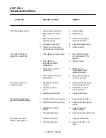
Page 43: ...e fuse control box investigate if fuses continue to blow 4 Motor starter overload 4 Reset and investigate heaters trip cause of overload Compressor does not 1 Improperly adjusted 1 Refer to Section 4...

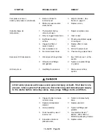
Page 44: ...es Excessive Oil Consumption 1 Oil carryover through lines 1 See Oil Carryover in this section 2 Oil leaks at all fittings 2 Tighten or replace fittings and gaskets or gasket Oil Carry Over 1 Overfill...

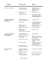
Page 45: ...um pressure 4 Disassemble and clean valve 5 Defective minimum 5 Rebuild or replace pressure valve Won t set at 65 psig 4 5 Bars CHANGE SEPARATOR light 1 Separator differential is 1 Change Separator Fl...

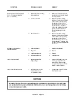
Page 46: ...d fault 2 Measure the AC voltage between wire number 7 and wire number 6 at board If the reading is 24 volts replace the control board MOTOR OVERLOAD 1 Loose connections 1 Measure the AC voltage shutd...

Page 47: ...ng transducer at the control board with zero pressure on the transducer If below 450 or over 550 volts replace the transducer Oil leak at the bottom of 1 Gasket leaking 1 Replace the gasket the seal h...

Page 48: ...SEAL 1 200EBB6029 8 KIT BEARING Includes 200EBB6029 1 200EBB6023 9 CAP Oil Filler 1 2116964 10 O RING 1 2117004 11 PLUG Hex Screw 2 2116942 12 WASHER 2 2116941 13 FILTER AIR Element Only 1 Refer to p...

Page 49: ...NAP RING 1 2116980 8 RETAINER 1 2116978 9 BUSHING 1 10 RING WEAR 1 2117033 11 SPRING 1 2117029 12 RING WEAR 1 2117032 13 PISTON 1 2116991 14 SCREW SO HD 1 2116995 15 RING PACKING 1 16 O RING 1 17 RING...

Page 50: ...Page 40 AIR FILTER 209EBB810 Ref Drawing Ref No Name of Part Qty Part No 1 WING NUT 1 2117034 2 CLOSE NIPPLE 1 2116987 3 COVER 1 2117028 4 AIR FILTER ELEMENT 1 200EBB059 5 HOUSING 1 2117027 6 O RING 1...

Page 51: ...of Part Qty Part No 1 GASKET 2 2 HOUSING 1 3 GUIDE PLUG 1 4 GASKET RING 1 7 SPRING 1 8 BUSHING 1 9 PISTON 1 10 CONTROLLER INTAKE 1 2116967 11 SCREW So Hd CAP 4 2116976 12 SEAL 1 KIT VALVE INTAKE Inclu...

Page 52: ...1 5 GUIDE SPRING 1 2116946 6 SPRING 1 2116947 7 O RING 1 8 PISTON CONTROL 1 9 SPRING VALVE 1 10 PLATE VALVE 1 11 UNION STRAIGHT 1 2116945 12 FILTER OIL 1 200EBB369 13 SEPARATOR AIR OIL 1 200EBB035 14...

Page 53: ...13 8 612 Page 43 PIPING AND MOUNTING GROUP 213EBB810 B Ref Drawing...

Page 54: ...5K5 15 VALVE BALL 1 90AR360 16 SCREW 4 655MD030 17 LOCKWASHER 4 95B4 18 GUARD FAN 1 200ECM393 19 BUSHING SHEAVE 1 22G27 20 FAN 1 200EBB701 21 GUARD FAN 1 200EBB393 Ref No Name of Part Qty Part No 22 S...

Page 55: ...00EBB285 2 PANEL 2 201EBB216 3 GUARD DRIVE 1 201EBB120 4 FRAME 1 202EBB314 5 HOOD 1 200EBB053 6 FRAME 1 203EBB314 7 BRACKET FORMED 2 200EBB142 8 BRACE 1 200EBB326 9 PLATE INSPECTION 1 300EBB052 10 PAN...

Page 56: ...13 8 612 Page 46 QUIET ENCLOSURE 202EBB810 B Ref Drawing Ref Part No No Name of Part Qty 203EBB4017 1 BAFFLE 1 202EBB840 3 SCREW FLANGED 4 75LM51...

Page 57: ...B863 5 CONNECTOR TUBE 1 86H139 86H139 6 BUSHING PIPE 1 64E11 64E11 7 NIPPLE 1 63H1G 63H1G 8 VALVE BALL 1 90AR362 90AR362 9 BUSHING PIPE 1 64E2G 64E2G 10 NIPPLE 1 63D1G 63D1G 11 TEE PIPE 1 64G3G 64G3G...

Page 58: ...TUBE 1 86H139 86H139 6 BUSHING PIPE 1 64E11 64E11 7 NIPPLE 1 63H1G 63H1G 8 VALVE BALL 1 90AR362 90AR362 9 BUSHING PIPE 1 64E2G 64E2G 10 NIPPLE 1 63D1G 63D1G 11 TEE PIPE 1 64G3G 64G3G 12 ELBOW 1 64D2G...

Page 59: ...210EBB4004 203EBB4004 204EBB4004 205EBB4004 1 VALVE PRESSURE RELIEF 1 90AR661 90AR662 90AR663 90AR657 2 SHEAVE 1 73M23V47 73M23V50 73M23V41 73M23V41 3 BUSHING HUB 1 22J4 22J6 22J4 22J4 4 SHEAVE 1 73M2...

Page 60: ...UBE 3 86N287 4 O RING 3 24A383 5 CONNECTOR TUBE 1 86E4 6 THERMISTOR PROBE 1 8 NPT 1 21D293 7 TEE PIPE 1 64G3G 8 NIPPLE 1 63D1G 9 ELBOW TUBE 1 86E78 10 TUBE 10 85K3 11 FITTING CABLE 2 24CA2865 12 FITTI...

Page 61: ...13 8 612 Page 51 ELECTRICAL GROUP 205EBB810 A Ref Drawing For Parts List Refer to Pages 52 thru 54...

Page 62: ...8 24CA4088 8 DECAL Fan Motor Fuse 1 309AUX077 308AUX077 306AUX077 306AUX077 9 FITTING CONDUIT Fan 1 24A380 24A380 24A380 24A380 10 CONDUIT Fan 2 24A402 24A402 24A402 24A402 11 FITTING CONDUIT Fan 1 24...

Page 63: ...4088 8 DECAL Fan Motor Fuse 1 309AUX077 308AUX077 306AUX077 306AUX077 9 FITTING CONDUIT Fan 1 24A380 24A380 24A380 24A380 10 CONDUIT Fan 2 24A402 24A402 24A402 24A402 11 FITTING CONDUIT Fan 1 24A378 2...

Page 64: ...088 8 DECAL Fan Motor Fuse 1 309AUX077 308AUX077 306AUX077 306AUX077 9 FITTING CONDUIT Fan 1 24A380 24A380 24A380 24A380 10 CONDUIT Fan 2 24A402 24A402 24A402 24A402 11 FITTING CONDUIT Fan 1 24A378 24...

Page 65: ...75 PLUG CONNECTOR 1 24CA3306 24CA3306 PLUG CONNECTOR 1 24CA3400 24CA3400 FUSE 1 24CA3725 24CA3726 TRANSFORMER 1 2116694 2116695 HOURMETER 1 24CA2895 24CA2895 OPERATOR 1 24CA2907 24CA2907 CONTACT BLOCK...

Page 66: ...MOTOR 200V 24CA674 MOTOR 230 460V 24CA678 MOTOR 575V 24CA681 MOTOR 200V 24CA675 MOTOR 230 460V 24CA679 MOTOR 575V 24CA682 BASE 24AZ34 24AZ34 24AZ35 MOTOR GROUP FAN MOTORS 60 HZ TEFC 7 5 HP 10 HP 15 H...

Page 67: ...VER PART NUMBER PART NUMBER H2002B 24CA4101 H2003B 24CA4102 H2004B 24CA4103 H2005B 24CA4104 H2006B 24CA4105 H2007B 24CA4106 H2008B 24CA4107 H2009B 24CA4108 H2010B 24CA4109 H2011B 24CA4110 H2012B 24CA4...

Page 68: ...77 DECAL WARNING HOT OIL UNDER PRESSURE 1 212EAQ077 DECAL LUBRICANT AEON 2000 1 253EAQ077 DECAL DANGER DO NOT MODIFY 1 218EAQ077 DECAL WARNING ROTATING MACHINERY 1 211EAQ077 DECAL WARNING AUTO RESTART...

Page 69: ...ELEMENT 1 200EBB035 MAINTENANCE KIT Minimum Pressure Check Valve 1 2116968 KIT VALVE Intake Maintenance 1 2116966 KIT BEARING Includes Oil Seal Kit 1 200EBB6023 KIT OIL SEAL 1 200EBB6029 KIT VALVE Int...

Page 70: ...cycled with the air compressor The fan on the air cooled unit will cycle in accordance with head pressure The refrigerant suction pressure gauge reading after start up and while operating under rated...

Page 71: ...rge pressure reaches 375 PSI This condition will cause the dryer unit to shutdown and the ALARM indicator to be lit The unit cannot be re started until the dryer compressor discharge pressure decrease...

Page 72: ...13 8 612 Page 62 FIGURE 11 4 REFRIGERATED DRYER FIGURE 11 5 SUCTION PRESSURE GAUGE DRYER INLET AND OUTLET...

Page 73: ...13 8 612 Page 63 FIGURE 11 6 CONDENSER HEAT EXCHANGER HOT GAS BYPASS FIGURE 11 7 COMPRESSOR REFRIGERATED DRYER...

Page 74: ...roperly by checking continuity read windings for continuity Dryer not running 1 Switch not turned on 1 Check switch Motor Run light is off 2 No power 2 Verify proper line voltage to unit 3 Circuit bre...

Page 75: ...eck unit for leaks using soap bubbles or electronic leak detector Repair leak 5 Low ambient temperature 5 Check fan operation Verify proper and fan not cycling operation of fan cycling control Moistur...

Page 76: ...per load and temperature Refrigerant at dryer inlet compressor OFF 2 Refrigerant shortage 2 Check for leaks using soap bubbles or electronic leak detector If leaks are detected repair immediately usin...

Page 77: ...13 8 612 Page 67 INTEGRATED DRYER ASSEMBLY AND PIPING 301EBB810 A Ref Drawing...

Page 78: ...8 VALVE BALL 1 90AR360 9 CONNECTOR TUBE 2 86H144 10 TUBE W FIT 1 302EBB863 11 DRYER AIR 1 300EBB463 12 ELBOW TUBE 1 86E78 13 TUBE 2 85K3 14 CONNECTOR TUBE 1 86N287 15 SCREW FLANGED 4 75LM98 16 NUT FLA...

Page 79: ...ASE 1 200EBB285 2 PANEL 2 201EBB216 3 GUARD DRIVE 1 201EBB120 4 FRAME 1 202EBB314 5 HOOD 1 301EBB053 6 FRAME 1 203EBB314 7 BRACKET FORMED 2 200EBB142 8 BRACE 1 200EBB326 9 PLATE INSPECTION 1 300EBB052...

Page 80: ...2 BLOCK 1 24CA4460 3 PUSHBUTTON SWITCH 1 24CA4459 4 SWITCH 1 24CA2886 5 CONTACTOR 1 24CA4453 6 CONTACT 1 24CA4461 7 RELAY 1 24CA2167 8 SOCKET 1 24CA2168 9 RELAY 1 24CA2169 10 RELAY 1 24CA4455 11 SOCK...

Page 81: ...OR 1 7000510 2 FAN BLADE 1 7000542 3 HEAT EXCHANGER 1 7003099 4 REFRIGERANT SERVICE VALVE 1 7000591 5 FAN CYCLE CONTROL 1 7000654 6 HIGH PRESSURE CONTROL 1 7000653 7 FILTER DRYER 1 7000599 8 HOT GAS V...

Page 82: ...13 8 612 Page 72 300EBB541 B Ref Drawing...

Page 83: ...gment is proved not to be as warranted Labor shall be limited to the amount specified in the Company s labor rate schedule Labor costs in excess of the Company rate schedule amounts or labor provided...

Page 84: ......
Reviews: