13–8–612 Page 28
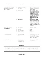
pressor cylinder is not clogged or pinched off, the check
valve in the oil return is functioning properly, and there
is not water or an oil/water emulsion in the oil.
Oil carry–over malfunctions of the oil separator are
usually due to using elements too long, heavy dirt or
varnish deposits caused by inadequate air filter ser-
vice, use of improper oil, or using oil too long for existing
conditions. Excessive tilt angle of the unit will also ham-
per separation and cause oil carry–over.
Oil separator element life cannot be predicted; it will
vary greatly depending on the conditions of operation,
the quality of the oil used and the maintenance of the
oil and air filters. The condition of the separator can be
determined by pressure differential or by inspection.
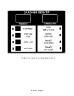
Pressure Differential Gauging – The “CHANGE
SEPARATOR” message will flash when the pressure
differential across the oil separator reaches approxi-
mately 8 PSI. Replace the oil separator element at this
time. If ignored, the unit will shut down and the display
will indicate shutdown and the change separator LED
will be on when the pressure differential reaches 15
PSI.
To measure the pressure differential, see “Pressure
and Temperature Digital Readouts” in Section 4, page
19. Simply subtract the downstream reading from the
upstream reading.
Using an oil separator element at ex-
cessive pressure differential can
cause damage to equipment. Replace
the separator when the “Change Sep-
arator” advisory appears.
A sudden drop of zero pressure differ-
ential or sudden heavy oil carryover
may indicate a ruptured element.
Inspection – After removal of separator element,
shine a light inside the element to reveal areas of heavy
dirt or varnish deposits or breaks (ruptures) in element
media.
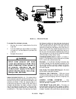
Removal Of Oil Separator For Inspection Or Re-
placement:
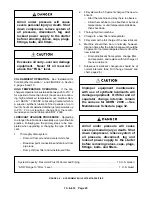
Air/oil under pressure will cause
severe personal injury or death. Shut
down compressor, relieve system of
all pressure, disconnect, tag and
lockout power supply to the starter
before removing valves, caps, plugs,
fittings, bolts, and filters.
1.
Be certain unit is off and all system pressure is re-
lieved.
2.
Disconnect, tag and lockout the power supply to
the starter.
3.
Remove spin–on element.
4.
Clean the gasket seating surface of the head.
5.
Inspect and/or replace the separator as neces-
sary. Before reassembly, coat the separator ele-
ment gasket with the same lubricant used in the
unit.
6.
Screw on until gasket makes contact. Hand tight-
en 1/3 to 1/2 turn extra.
7.
Run the unit and check for leaks.
Oil Scavenge Site Glass – During operation the per-
formance of the oil separator can be monitored through
the oil site glass in the scavenge line. The site glass
shows the oil being returned to the air end. When the
unit is started, “Full Oil” is shown, due to oil accumula-
tion in the separator. After a few minutes, only a small
amount of oil will be seen. This signifies that the air/oil
separator is working properly.
COMPRESSOR OIL SYSTEM CHECK – The follow-
ing readings are based on ambient temperature of 80
_
F with the system in good condition. The compressor
should be at operating temperature at the time of the
checks. One–half hour of loaded operation is usually
sufficient to reach level–out operating temperatures.
Air and Oil Discharge Temperature – 170
_
to 200
_
F – Read at the gauge on the instrument panel or check
with a thermometer at the discharge housing.
Compressor Oil Inlet Temperature – 165
_
to 175
_
F
– Install a tee at oil filter outlet and check with a ther-
mometer.
Summary of Contents for EBB BB-7.5 HP
Page 12: ...13 8 612 Page 2 FIGURE 1 2 PACKAGE COMPRESSOR MOTOR SIDE FIGURE 1 3 PACKAGE BELT GUARD SIDE...
Page 13: ...13 8 612 Page 3 FIGURE 1 4 PACKAGE CONTROLLER END...
Page 16: ...13 8 612 Page 6 DECALS 206EAQ077 212EAQ077 218EAQ077 211EAQ077 207EAQ077...
Page 17: ...13 8 612 Page 7 DECALS 216EAQ077 217EAQ077 222EAQ077 221EAQ077 208EAQ077...
Page 32: ...13 8 612 Page 22 FIGURE 4 7 AUTO SENTRY S SOLID STATE CONTROL TOUCH PAD...
Page 33: ...13 8 612 Page 23 200EBB546 Ref Drawing FIGURE 4 8 WIRING DIAGRAM...
Page 53: ...13 8 612 Page 43 PIPING AND MOUNTING GROUP 213EBB810 B Ref Drawing...
Page 77: ...13 8 612 Page 67 INTEGRATED DRYER ASSEMBLY AND PIPING 301EBB810 A Ref Drawing...
Page 82: ...13 8 612 Page 72 300EBB541 B Ref Drawing...
Page 84: ......


