


13–8–612 Page 11
tween the unit and the customer’s air system. If a fast
operating valve, such as a ball valve, is used, it must
be closed slowly to give the intake valve time to shut
and keep the discharge pressure from spiking. When
manifolding two or more Electra–Screw
units on the
same line, each unit is isolated by the check valve in the
unit discharge line. If an Electra–Screw
unit is man-
ifolded to another compressor, be sure the other com-
pressor has a check valve in the line between the ma-
chine and the manifold. If an Electra–Screw
and a
reciprocating compressor are manifolded together, an
air receiver must be located between the two units.
Discharge air used for breathing will
cause severe injury or death.
Consult filtration specialists for addi-
tional filtration and treatment equip-
ment to meet health and safety stan-
dards.
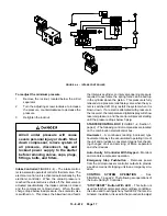
ELECTRICAL WIRING – Standard Units – The Elec-
tra–Screw
compressor is factory wired for all starter
to motor and control connections for the voltage speci-
fied on the order. It is necessary only to connect the unit
starter to the correct power supply. The standard unit
is supplied with an open drip–proof motor, a NEMA 1
starter and control enclosure. See “Location”, page 8,
for the distance to the nearest obstruction on the starter
and control box sides of the unit.
Terminals for incoming power are located on the con-
tactor behind the fan motor fuse block. To remove the
fuse block, locate the locking tab on the back side and
press forward, then slide the fuse block up and off of the
contactor. Connect incoming power leads to L1, L2 and
L3 on the contactor. Replace the fuse block by sliding
back down on the mounting track until the locking tab
snaps and hold it in place.
Do not connect incoming power to
the fan motor fuse box.
The overload heaters are to be selected according to
starter manufacturer’s tables, which are attached to
the inside of the control box, based on motor nameplate
full load amperage.
Electrical shock can cause injury or
death. Open main disconnect switch,
tag and lockout before working on
starter/control box.
GROUNDING – Equipment must be grounded in ac-
cordance with Section 250 of the National Electrical
Code.
Failure to properly ground the com-
pressor package could result in con-
troller malfunction.
MOTOR LUBRICATION – Long time satisfactory op-
eration of an electric motor depends in large measure
on proper lubrication of the bearings. The following
charts show recommended grease qualities and re-
greasing intervals for ball bearing motors. For addition-
al information refer to the motor manufacturer’s
instructions. The following procedure should be used
in regreasing:
1.
Stop the unit.
2.
Disconnect, tag and lockout the unit from the
power supply.
3.
Remove the relief plug and free hole of hardened
grease.
4.
Wipe lubrication fitting clean and add grease
with a hand–operated grease gun.
5.
Leave the relief plug temporarily off. Reconnect
unit and run for about 20 minutes to expel the ex-
cess grease.
6.
Stop the unit. Replace the relief plug.
7.
Restart the unit.
Rotating machinery can cause injury
or death. Open main disconnect, tag
and lockout power supply to the start-
er before working on the electric mo-
tor.
Summary of Contents for EBB BB-7.5 HP
Page 12: ...13 8 612 Page 2 FIGURE 1 2 PACKAGE COMPRESSOR MOTOR SIDE FIGURE 1 3 PACKAGE BELT GUARD SIDE...
Page 13: ...13 8 612 Page 3 FIGURE 1 4 PACKAGE CONTROLLER END...
Page 16: ...13 8 612 Page 6 DECALS 206EAQ077 212EAQ077 218EAQ077 211EAQ077 207EAQ077...
Page 17: ...13 8 612 Page 7 DECALS 216EAQ077 217EAQ077 222EAQ077 221EAQ077 208EAQ077...
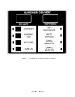
Page 32: ...13 8 612 Page 22 FIGURE 4 7 AUTO SENTRY S SOLID STATE CONTROL TOUCH PAD...
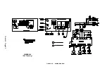
Page 33: ...13 8 612 Page 23 200EBB546 Ref Drawing FIGURE 4 8 WIRING DIAGRAM...
Page 53: ...13 8 612 Page 43 PIPING AND MOUNTING GROUP 213EBB810 B Ref Drawing...
Page 77: ...13 8 612 Page 67 INTEGRATED DRYER ASSEMBLY AND PIPING 301EBB810 A Ref Drawing...
Page 82: ...13 8 612 Page 72 300EBB541 B Ref Drawing...
Page 84: ......