background image

Installation  Guide 


42 


Follow the steps below to mount the PTZ Camera with the Mini Pendent Mount. 


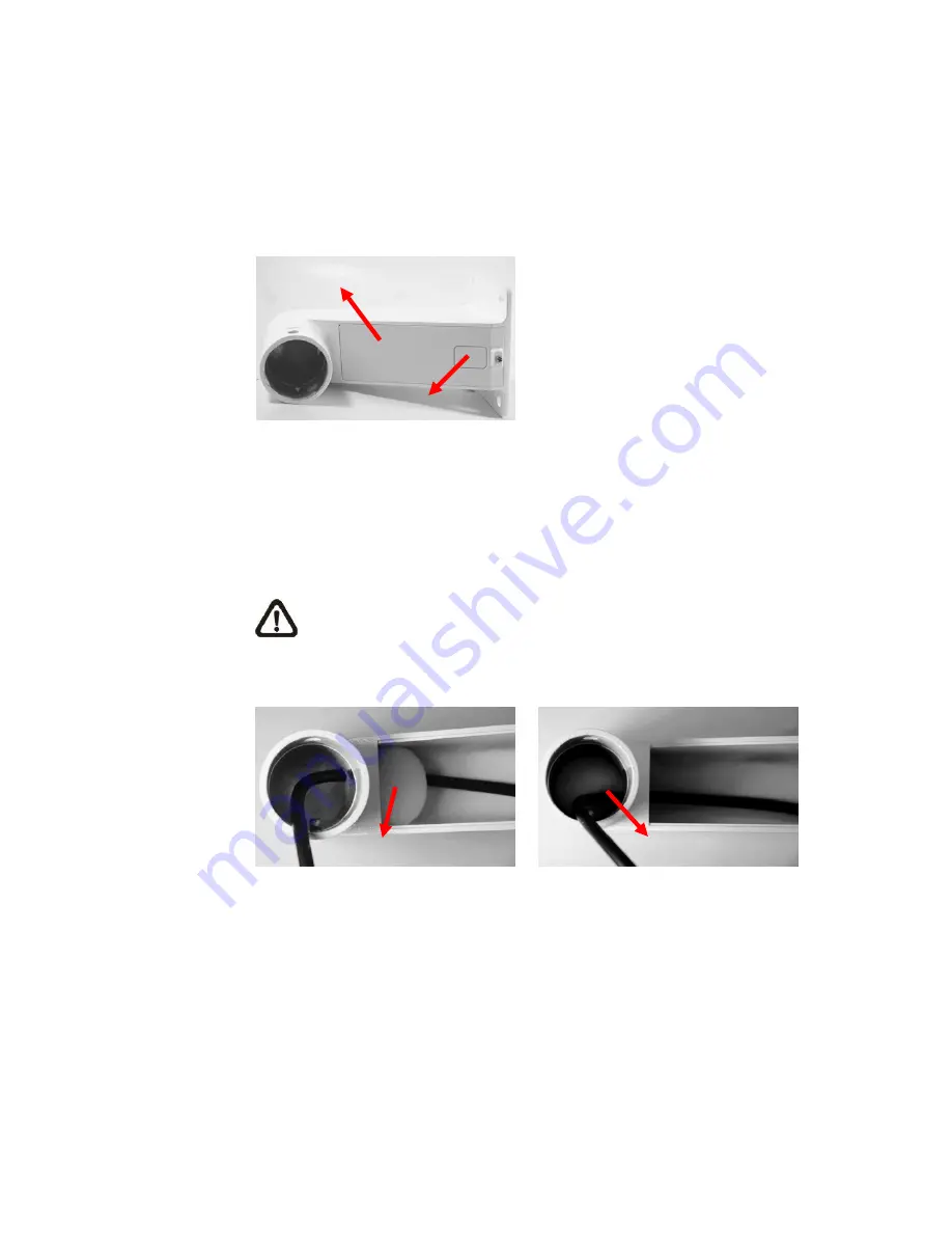
1)  Make a cable entry hole on the wall to recess the cables. Otherwise, users could 

push up the Cable Entry Board on the Mini Pendent Mount’s Mounting Plate to 

place the cables, as shown in the photo below.   


2)  Fix the Mini Pendent Mount on the wall with proper screws and screw anchors. 

3)  Attach the Waterproof Rubber to the Mini Pendent Mount. 

4)  Run  the  cable(s) through  the  Mini  Pendent  Mount  with  the  Data  Cable’s  22-pin 

cable coming out of the outlet. 


NOTE:  Please  block  the  cable  entry  hole  with  the  supplied  sponge  to 

avoid insects entering the Pendant Mount. The sponge can be placed in 

two ways as shown in the illustrations below. 


5)  Thread the cable(s) through the Indoor Mount Kit and join the Indoor Mount Kit to 

the Mini Pendent Mount with the supplied screws and washers. Then adjust the 

Waterproof Rubber to the joint. 

6)  Connect the cable(s) to the PTZ Camera. 

7)  Join  the  PTZ  Camera  to  the  Indoor  Mount  Kit  with  the  supplied  screw  and 

washers. 


Mounting Plate


Cable Entry Board


Sponge


Sponge


Summary of Contents for ZC-PT236

Page 1: ......

Page 2: ...manual with the original bill of sale for future reference and if necessary warranty service When unpacking your unit check for missing or damaged items If any item is missing or if damage is evident...

Page 3: ...produits lectriques et lectroniques doivent tre limin s s par ment de la cha ne de collecte municipale des ordures par l interm diaire des installations de collecte prescrites et d sign es par le gou...

Page 4: ...enziata per l avvio successivo dell apparecchiatura dismessa al riciclaggio al trattamento e allo smaltimento ambientalmente compatibile contribuisce ad evitare possibili effetti negativi sull ambient...

Page 5: ...de elimina o de res duos ou a loja onde comprou o produto Espa ol Spanish C mo deshacerse de aparatos el ctricos y electr nicos viejos 1 Si en un producto aparece el s mbolo de un contenedor de basura...

Page 6: ...mera and may cause malfunction Do not operate the camera beyond the specified temperature humidity or power source ratings Use the indoor camera under conditions where temperature is between 0 40 C 32...

Page 7: ...on 22 4 1 PTZ Camera Dimension 22 4 2 Optional Accessories 23 4 3 Ceiling Mount 31 4 3 1 Hard Ceiling Mounting Indoor 32 4 3 2 In Ceiling Mounting Indoor 35 4 3 3 In Ceiling Mounting with Ceiling Pane...

Page 8: ...Installation Guide 7 6 System Integration 68 6 1 Using Pelco Keyboard 68 6 2 Using Phillips Allegiant Keyboard 70 Appendix A Technical Specification 72...

Page 9: ...ZC PT236 Model 36 optical zoom 12 digital magnification ZC PT235 Model 35 optical zoom 12 digital magnification ZC PT230 Model 30 optical zoom 12 digital magnification ZC PT226 model 26 optical zoom 1...

Page 10: ...distance up to 1 2 km 4000 feet and to protect the connected devices it is highly recommended to place a repeater at the mid point However a repeater may be needed in the network distance less than 1...

Page 11: ...y item is missing or if damage is evident DO NOT install or operate the product and contact your dealer for assistance Indoor PTZ Camera Standard Package Camera Body Hard Ceiling Mount and Decoration...

Page 12: ...de 11 Outdoor PTZ Camera Standard Package Camera Body with Outdoor Mount Kit Screws Security screw set Water proof rubber Lubricant Cable for Power Video RS 485 and Alarm Power Cord Installation Guide...

Page 13: ...steps below to remove those protective materials Step 1 Unpack the PTZ Camera s package and take out the camera body Step 2 Rotate the dome cover Step 3 Remove the PE cloth sheet and take off the lens...

Page 14: ...nt on the cover s water proof rubber to make the installation process smoother Note that the tiny protrusion on the camera cover must align with one of the four holes on the camera body STEP 5 Gently...

Page 15: ...uide 14 STEP 6 Screw the camera cover and body together STEP 7 Set the switches located on the bottom of the camera body Refer to section 3 3 PTZ Camera Setups for detailed information about various s...

Page 16: ...lowing figures and table for switch location and definitions Indoor PTZ Camera Outdoor PTZ Camera A Camera Control Protocol Switch B Communication Switch C None D 22 Pin Connector E ID Switch F Reserv...

Page 17: ...3 3 PTZ Camera ID Setting Please change the camera ID if there is more than one camera on the same installation site To change your camera ID please turn the arrow of the ID switch to a desired number...

Page 18: ...PT 9600 08 AD422 4800 09 DM P 9600 11 Pelco D 4800 12 Pelco D 9600 13 Pelco P 2400 14 Pelco P 9600 15 JVC 9600 16 GANZ S 4800 17 GANZ S 9600 18 GANZ S 19200 19 GANZ S 38400 21 Kalatel 485 9600 22 Kal...

Page 19: ...ial cable to send video signals is recommended RS 485 cable carries commands from a control device to the dome cameras A CAT 5 24 gauge cable is recommended Power supply AC 24V output voltage NOTE Ens...

Page 20: ...h pin please refer to the list below Pin Definition Cable Pin Definition Cable 1 AC 24 1 20AWG 18AWG 12 ALM 1 2 ALM NC 13 ALM 3 3 AC 24 2 20AWG 18AWG 14 ALM 2 4 ALM NO 15 ALM 4 5 FG 20AWG 18AWG 16 ALM...

Page 21: ...e recommended cables for RS 485 communication are CAT 5 cables maximum cable length for over 24 gauge wire is 4000 feet 1219 meters If the total cable length exceeds 4000 feet using a repeater to main...

Page 22: ...e table follows will illustrate the way to wire cords into the connector housing Please refer to the section 3 4 3 22 Pin Connector Definition for the exact position of each cord Insert the terminal i...

Page 23: ...In the following sections various installation accessories installation methods and installation procedures will be described in detail 4 1 PTZ Camera Dimension The indoor PTZ camera s dimensions are...

Page 24: ...6VA ZCA 220 1 5A Input 220 230VAC Output 24VAC 36VA NOTE When wiring make sure the G Y wire Ground inserted into the mid pin of the terminal block Outdoor PTZ Camera Accessories Sunshield ZCA SSH equi...

Page 25: ...sories Hard Ceiling Mount ZCA HC200 Indoor Camera For Hard Ceiling use Height 21 4mm Diameter of the three holes 4 5mm Diameter of the bracket 158mm Indoor Mount Kit ZCA IPA Indoor Camera For mounting...

Page 26: ...er 180 mm 7 1 inches 0 5 kg 1 1 lbs Ceiling Panel For ceiling mounting Zn platted 610 305 mm 24 12 inches Diameter 135 mm 5 3 inches Standard Pendent Mount White 348 104 138 6 mm 13 7 4 1 5 5 inches 1...

Page 27: ...ght Tube ZCA ST25 ST50 Indoor Outdoor White Iron Height 250 500 mm 9 8 19 7 inches Diameter 50 mm 2 inches 1 kg 2 2 lbs 1 8 kg 4 lbs Supplied with rubber washer 8 1 pendant tube washer 1 spring waher...

Page 28: ...Corner Standard Mounting Plate ZCA CST Indoor Outdoor White 222 L 204 W 117 D mm 8 7 8 4 6 inches 2 kg 4 4 lbs Supplied with washer 8 4 spring washer 4 M8 20 screw 4 M8 nut 4 Pole Thin Direct Mountin...

Page 29: ...tainless steel straps 4 M8 16 screw 4 washer 4 spring washer 4 Corner Thin Box ZCA CTB Indoor Outdoor White 300 L 164 W 222 D mm 11 8 6 5 8 7 inches 3 kg 6 7 lbs Supplied with washer 4 M8 16 screw 4 a...

Page 30: ...asher 4 stainless steel straps 4 Pole Wide Box ZCA PWB Indoor Outdoor White 270 L 166 W 155 D mm 10 6 6 5 6 1 inches 3 2 kg 7 1 lbs Supplied with M8 16 screw 4 washer 4 spring washer 4 stainless steel...

Page 31: ...nverter ZCA RS422 485 RS 485 RS 232 Repeater ZCA RS232 485 RS 232 between RS 485 RS 422 ZCA BP 485 Bi phase to RS 485 RS 422 ZCA RS422 485 ZCA RS232 485 ZCA BP 485 Power Box White 186 5 147 mm 7 3 5 8...

Page 32: ...hes 4 3 Ceiling Mount Generally there are three kinds of ceiling mounting methods hard ceiling in ceiling and mounting with straight tube Refer to the following sections for more detailed information...

Page 33: ...ems and tools needed to mount the Camera onto the ceilings The supplied items are all in the PTZ Camera package Items Needed PTZ Camera Hard Ceiling Mount and Decoration Ring Supplied Fixing Plate Sup...

Page 34: ...rill these holes on the hard ceiling STEP 5 Fix the Mount to the holes on the hard ceiling with three screws STEP 6 Thread the data cable through the center hole of the Mount and connect the cable to...

Page 35: ...Installation Guide 34 STEP 8 Fix the decoration ring to the bracket NOTE Make sure the optical cover is removed before carrying out the procedure STEP 9 Place the optical cover back...

Page 36: ...ndard PTZ Camera package Items Needed PTZ Camera T Bar Optional Accessory Supplied Screw Equipped with T Bar Red Sticker Equipped with T Bar Decoration Ring Equipped with Hard Ceiling Mount as standar...

Page 37: ...iling STEP 4 Put up the T Bar into the ceiling opening STEP 5 Rotate T Bar wings of the hinge to fix the T Bar at the edge of the ceiling opening STEP 6 Tighten the screws and the T Bar wings will adh...

Page 38: ...fore carrying out the procedure 4 3 3 In Ceiling Mounting with Ceiling Panel To mount the PTZ camera to a suspended ceiling with the T Bar the ceiling panel could be employed as shown in the figure be...

Page 39: ...drilling Tool for screwing Follow the steps to mount the PTZ Camera with the Straight Tube 1 Ensure that the ceiling can support the weight of the PTZ Camera and Straight Tube 2 Make a cable entry ho...

Page 40: ...t the cables to the PTZ Camera 9 Mount the PTZ Camera to the Indoor Mount Kit Ensure the PTZ Camera is fixed completely and the thread holes on the Lock Screw Plate and Indoor Mount Kit are aligned Af...

Page 41: ...the ceiling 3 Fix the Straight Tube to the ceiling with proper screws and screw anchors 4 Attach the Waterproof Rubber to the Straight Tube 5 Run the cable s through the Straight Tube with the Data Ca...

Page 42: ...structions below for mounting the PTZ Camera via different ways 4 4 1 Mini Pendant Mount ZCA GT100 Indoor PTZ Camera Items Needed PTZ Camera Data Cable supplied Mini Pendent Mount and equipped items o...

Page 43: ...he cable s through the Mini Pendent Mount with the Data Cable s 22 pin cable coming out of the outlet NOTE Please block the cable entry hole with the supplied sponge to avoid insects entering the Pend...

Page 44: ...plied M5 Standard Security Screw supplied Screws and Screw Anchors for fixing the Mini Pendent Mount not supplied Tools Needed Tool for drilling Tool for screwing Follow the steps below to mount the P...

Page 45: ...ith the supplied sponge to avoid insects entering the Pendent Mount The sponge can be placed in two ways as shown in the illustrations below 5 Thread the cable s through the Outdoor Mount Kit and join...

Page 46: ...Mount Kit s accessory Screws and Screw Anchors for fixing the Standard Pendent Mount onto the ceiling not supplied Tools Needed Tool for drilling Tool for screwing Follow the steps below to mount the...

Page 47: ...y hole with the supplied sponge to avoid insects entering the Pendent Mount See the illustrations in section 4 4 1 Mini Pendent Mount Step 4 5 Thread the cable s through the Indoor Mount Kit and join...

Page 48: ...the cables see the illustration in section 4 4 1 Mini Pendent Mount Step 1 2 Fix the Standard Pendent Mount on the wall with proper screws and screw anchors 3 Attach the Waterproof Rubber to the Stand...

Page 49: ...accessory Wall Box Mounting optional accessory Indoor Mount Kit optional accessory Waterproof Rubber Indoor Mount Kit s accessory Screws and Screw Anchors for fixing the Wall Box Mounting onto the cei...

Page 50: ...E Please block the cable entry hole with the supplied sponge to avoid insects entering the Pendent Mount See the illustrations in section 4 4 1 Mini Pendent Mount Step 4 4 Attach the Waterproof Rubber...

Page 51: ...rough the hole on the Wall Box Mounting with the Data Cable s 22 pin cable coming out 3 Fasten the Standard Mini Pendent Mount onto the Wall Box Mounting with the supplied screws and washers Then thre...

Page 52: ...TZ Camera Data Cable supplied Standard Mini Pendent Mount and equipped items optional accessory Standard Mini Corner Mounting Plate herein collectively called Corner Mounting Plate optional accessory...

Page 53: ...ndard Mini Pendent Mount with the cable s coming out of the Pendent Mount s outlet NOTE Please block the cable entry hole with the supplied sponge to avoid insects entering the Pendent Mount See the i...

Page 54: ...rew anchors Then run the cable s through the hole on the Corner Mounting Plate with the Data Cable s 22 pin cable coming out 3 Fasten the Standard Mini Pendent Mount onto the Corner Mounting Plate wit...

Page 55: ...Mount and equipped items optional accessory Corner Thin Wide Box optional accessory Indoor Mount Kit optional accessory Waterproof Rubber Indoor Mount Kit s accessory Screws and Screw Anchors for fix...

Page 56: ...tlet NOTE Please block the cable entry hole with the supplied sponge to avoid insects entering the Pendent Mount See the illustrations in section 4 4 1 Compact Pendent Mount Step 4 4 Attach the Waterp...

Page 57: ...through the hole on the Corner Mounting Plate with the Data Cable s 22 pin cable coming out 3 Fasten the Standard Mini Pendent Mount onto the Corner Thin Wide Box with the supplied screws and washers...

Page 58: ...era Items Needed PTZ Camera Data Cable supplied Standard Mini Pendent Mount and equipped items optional accessory Pole Thin Wide Direct Mounting optional accessory Indoor Mount Kit optional accessory...

Page 59: ...ount with the cable s coming out of the Pendent Mount s outlet NOTE Please block the cable entry hole with the supplied sponge to avoid insects entering the Pendent Mount See the illustrations in sect...

Page 60: ...e Thin Wide Direct Mounting with the Data Cable s 22 pin cable coming out 3 Fasten the Standard Mini Pendent Mount onto the Pole Thin Wide Direct Mounting with the supplied screws and washers Then thr...

Page 61: ...l accessory Indoor Mount Kit optional accessory Waterproof Rubber Indoor Mount Kit s accessory Stainless Steel Straps for fixing the Pole Thin Wide Box Mounting optional accessory Tools Needed Stainle...

Page 62: ...Pendent Mount See the illustrations in section 4 4 1 Compact Pendent Mount Step 4 4 Attach the Waterproof Rubber to the Standard Mini Pendent Mount 5 Thread the cable s through the Indoor Mount Kit a...

Page 63: ...Box Mounting with the Data Cable s 22 pin cable coming out 3 Fasten the Standard Mini Pendent Mount onto the Pole Thin Wide Box Mounting with the supplied screws and washers Then thread the cable s th...

Page 64: ...Installation Guide 63 Pole Box Mounting Pole Thin Wide Box Standard Mini Pendent Mount Outdoor Mount Kit...

Page 65: ...other devices for easy installation To connect the connector box with other devices Use a RS 485 cable CAT 5 is recommended to complete RS 485 communication wiring with control devices such as DVRs an...

Page 66: ...models are available 100 115V AC power input P1030 and 220 230V AC P2030 Additionally users can either connect one camera to one power box and to Internet or to other control devices DVR Control Keybo...

Page 67: ...protected by the repeaters converters Up to 10 devices are allowed to connect to one repeater converter For detailed information please refer to the repeater converter user s manual ZCA RS422 485 RS 4...

Page 68: ...with cameras up to 1 kilometer away Additionally the SDU can be installed in either star or daisy chain configuration with up to 160 cameras see the diagrams below Its versatile installation configur...

Page 69: ...y the OSD menu ENTER Iris Open 9 5 hold Preset To send a ENTER command press Iris Open or 9 5 hold Preset Set and execute PRESET Hold Preset To set Preset hold the key Preset Preset To execute a prese...

Page 70: ...trol device The recommended cables for RS 485 communication are CAT 5 cables maximum cable length for over 24 gauge wire is 4000 feet 1219 meters If the total cable length exceeds 4000 feet using a re...

Page 71: ...er 7 7 shot Press the keys ON 4 6 Enter or 7 7 shot to display the OSD menu ENTER Iris 7 7 shot To send a ENTER command press Iris Open Close or 7 7 shot Set and execute PRESET set To set Preset use t...

Page 72: ...Pan please enter the OSD and go to the Auto Pan setting menu 7 9 8 2 shot The following Presets allows you to execute Auto Pan quickly 7 9 shot Auto Pan 1 8 0 shot Auto Pan 2 8 1 shot Auto Pan 3 8 2 s...

Page 73: ...6 82 8 mm 3 5 91 mm 3 4 119 mm Focus Mode Auto Manual White Balance Auto Manual Iris Control Auto Manual NTSC 1 1 1 10k sec 1 2 1 30k sec 1 1 1 10k sec 1 1 1 30k sec Electronic Shutter PAL 1 1 1 10k...

Page 74: ...n Cruise GENERAL Environment Indoor Outdoor Controller Interface RS 485 Indoor 0 C 40 C 32 F 104 F Operating Temperature Outdoor 50 C 50 C 58 F 122 F Waterproof Standard IP66 standard Indoor 131 x 226...

Page 75: ...rotocols TCP IP UDP HTTP FTP SMTP ARP ICMP DHCP RTP RTSP Alarm 4 digital alarm inputs 1 alarm output Alarm Reaction Preset Sequence Auto Pan Cruise Security User Account and Password Protection Suppor...

Page 76: ...Focal Length 3 4 61 2 mm 3 4 102 mm 3 4 122 4 mm Focus Mode Auto Manual White Balance Auto Manual Iris Control Auto Manual Electronic Shutter 1 1 1 10k sec AGC control Auto Manual Back Light Compensat...

Page 77: ...NERAL Environment Indoor Outdoor Controller Interface RS 485 Indoor 0 C 40 C 32 F 104 F Operating Temperature Outdoor 45 C 50 C 49 F 122 F Waterproof Standard IP66 standard Outdoor type Indoor 131 x 2...

Page 78: ...Installation Guide 77...

Reviews: