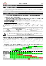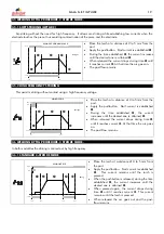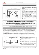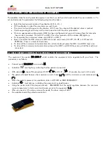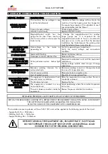
GALA G.E. TIG PULSE
16
3. START-UP. ADJUSTMENT AND OPERATION CONTROLS.
3.1 OPERATION CONTROLS.
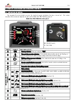
The equipment can be started up once the electrical supply installation has been carried out. This section
describes the control and adjustment system of the GALA G.E. TIG PULSE equipment.
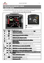
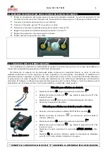
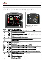
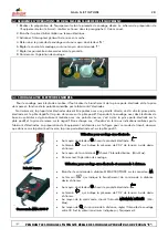
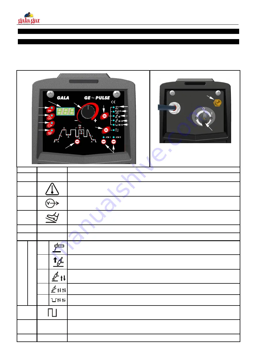
GALA G.E. TIG PULSE Control panel.
A
B
C
D
E
F
G
H
I
J
G1
G2
G3
G4
G5
K
L
K
- ON/OFF switch.
L
– Gas intake
Mark
Symbol
Description of use.
A
ON
Start-up indicator. Start-up indicator, “ON”.
B
Thermal disconnection indicator. This indicates disconnection due to overheating, or
due to the existence of a power supply voltage outside the nominal range.
C
Welding voltage presence indicator. This indicates the presence of voltage in the
welding connectors.
D
Remote control indicator connected. One of the remote controls available has been
connected (sections 3.2, 3.3 and 3.9).
E
Parameter value indicator / Real welding current.
F
Value selector.
G.1
ELECTRODE MODE. In this mode, the HOT START, ARC FORCE, and ANTI-STICKING
functions will be available. (Section 3.3)
G.2
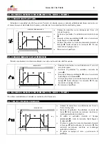
TIG 2 stroke MODE with striking by LIFT ARC. (Section 3.5)
G.3
TIG 2 stroke MODE with striking by High Frequency (HF). (Section 3.5)
G.4
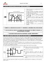
TIG 4 stroke MODE with striking by High Frequency (HF). (Section 3.6)
WELD
ING PROCESS
SEL
ECTOR:
G
G.5
TIG 4 stroke MODE with striking by High Frequency with possibility of 2 current levels.
(Section 3.6.2)
H
Selector and indicator of pulsed arc. (Section 3.7)
I
JOB
Parameter memorisation. (Section 3.8)
J
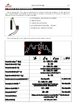
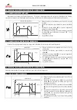
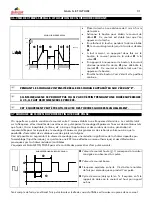
TIG process parameters. Sections 3.4 to 3.8.

