


IV
SUPPORTIVE GRAPHS
52
V/F curve for Normal door
52
V/F curve for Heavy door
52
V/F curve for Narrow door
53
DC Injection
53
Stall Reverse detection
54
Frequency Failure detection
54
Infrared Detector Edges detection
54
Edges Timeout relay and Buzzer timing
55
Edges Timeout relay and Buzzer mode
55
Interaction between Re-open and Edges Timeout relay
56
FAULTS LIST
57
FAULTS RESET HANDLING FLOWCHART
61
CLUTCH ENGAGED DISTANCE SETUP
62
DOOR STALL FORCE MEASUREMENT
63
CODE DISTANCE CLOSING TIME SETUP
64
MINIMUM CLOSING TIME (ECI REFERENTIAL VALUE)
65
CHECKING PROCEDURE FOR THE CLOSING CODE TIMES
66
INTERFACING BETWEEN ECI CERTIFIED LIGHT CURTAIN AND VFE2500
67
Understanding the RE-OPEN relay
67
How to interface between the Infrared Detector Edges and VFE2500
67
Test the Infrared Detector Edges
67
If the Detector Edges function does not work
68
If the Detector Edges have intermittent problems
68
Infrared Detector Edges connection
69
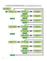
INFRARED DETECTOR EDGES APPLICATION FLOWCHART
70
OPTIONAL APPLICATIONS
HEAVIER DOOR
71
NARROWER DOOR
72
NARROWER DOOR APPLICATION FLOWCHART
73
NUDGING
74
NUDGING APPLICATION FLOWCHART
75
SERIAL COMMUNICATION
76
PARTS LIST
77
NOTES & COPYRIGHT
85
IV
Summary of Contents for MOVFE 2500
Page 1: ...2500 3069 1 888 425 2262 2500 3069 ELECTRICAL...
Page 2: ...Rev 1 10 20 I...
Page 24: ...19 6 DEFAULT PARAMETERS 19...
Page 26: ...21 FAULTS AN EXAMPLE OF FAULTS DISPLAY COUNTERS 21...
Page 27: ...22 USER LIST 22...
Page 28: ...23 23...
Page 29: ...24 24...
Page 30: ...25 25...
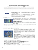
Page 31: ...26 MAXIMUM CLOSE SPEED AND FORCE 26...
Page 32: ...27 ECI DEFAULT PARAMETER SETS 27...
Page 34: ...29 SPEED PROFILES OF THE VFE2500 FOR NORMAL DOOR 29...
Page 35: ...30 SPEED PROFILES OF THE MOVFE2500 FOR HEAVY DOOR 30...
Page 36: ...31 SPEED PROFILES OF THE MOVFE2500 FOR NARROW DOOR 31...
Page 91: ...Rev 10 20 85...
Page 92: ......


