


9
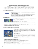
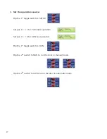
DEFAULT VALUE FOR THE ENCODER DIRECTION OF PAR. 42
HARMONIC
LINEAR
STRAIGHT GEARED
LEFT RIGHT CENTER LEFT RIGHT
CENTER LEFT RIGHT CENTER
2 1 2 1 2 1
1 1 2
10.
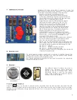
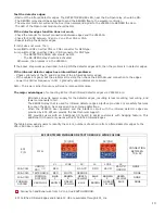
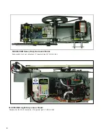
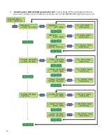
LEARN DOOR WIDTH LED:
11.
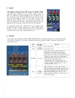
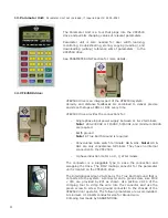
CAN Bus card:
12.
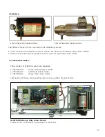
Infrared Detector Edges Connection Ports:
The “LEARN DOOR WIDTH” LED is an indicator to show the status of the door width
learning process.
To learn the Door Width:
Set Par. 63=1. Use Manual mode to run the door from DOL to DCL or vice versa.
Follow the prompts on the LCD display. The “LEARN DOOR WIDTH” LED will flash and
turn off when the learning process is completed. Par. 63 will reset itself to Zero.
See Parameter Adjustment section for more details.
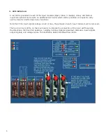
The optical galvanic isolation CAN bus card is one of the methods to interface
between and the elevator controller and the VFE2500. This total isolation helps
increase the reliability of the CAN bus.
To enable CAN Bus operation:
Flip the RUN| SETUP switch to SETUP. Set Par. 11 = 5.
Flip the RUN| SETUP switch to RUN. Flip the AUTO|MAN to AUTO to run VFE2500
with the CAN Bus.
Other communication protocols are also available upon request. However, an agreement between ECI and the
requesting party must be made prior to the implementation of the communication protocols.
Contact ECI for more details in CAN or other protocols.
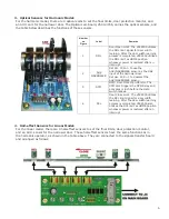
To simplify connections between infrared detector edges and the elevator
controller, ECI offers ECI Certified Infrared Detector Edges. These infrared
detector edges can be connected directly to the VFE2500. The procedure
below will assist users to plug and play ECI Certified Infrared Detector
Edges with the VFE2500.
NPN or PNP output:
The info of NPN or PNP output should be obtained prior to installation.
Read the label on the tube or the detector edges’ manual to know the
output type of the infrared detector edges. It is either NPN or PNP. Set the
selector switch SW8 accordingly. If the info of NPN or PNP is unavailable,
then, use a trial and error method. Assume that the edges’ output is NPN
for the 1
st
trial.
To set up ECI certified infrared detector edges:
Set Par. 202 = 1 for NPN type. Set Par. 202 = 2 for PNP type.
Set par. 202 = 0 to disable or should detector edges are not connected to the VFE2500.
Make sure the ENABLE CHIP is inserted into the socket U5 on the VFE2500 as shown.
Connect the ECI Certified Infrared Edges to connectors CN4 and/or CN5.
Note! Connectors CN4 and CN5 are interchangeable.
Make sure the REOPEN circuit is connected to the REOPEN output contacts as shown in section 6.
9
Summary of Contents for MOVFE 2500
Page 1: ...2500 3069 1 888 425 2262 2500 3069 ELECTRICAL...
Page 2: ...Rev 1 10 20 I...
Page 24: ...19 6 DEFAULT PARAMETERS 19...
Page 26: ...21 FAULTS AN EXAMPLE OF FAULTS DISPLAY COUNTERS 21...
Page 27: ...22 USER LIST 22...
Page 28: ...23 23...
Page 29: ...24 24...
Page 30: ...25 25...
Page 31: ...26 MAXIMUM CLOSE SPEED AND FORCE 26...
Page 32: ...27 ECI DEFAULT PARAMETER SETS 27...
Page 34: ...29 SPEED PROFILES OF THE VFE2500 FOR NORMAL DOOR 29...
Page 35: ...30 SPEED PROFILES OF THE MOVFE2500 FOR HEAVY DOOR 30...
Page 36: ...31 SPEED PROFILES OF THE MOVFE2500 FOR NARROW DOOR 31...
Page 91: ...Rev 10 20 85...
Page 92: ......


