1
Governors America Corp. © 2020 Copyright All Rights Reserved
ESD5500E Series Speed Control Unit 9-2020-F PIB1002
ESD5500E Series
Speed Control Unit
1
2
INTRODUCTION
SPECIFICATIONS
Performance
Isochronous Operation
± 0.25 % or better
Speed Range / Governor
1 - 7.5 kHz Continuous
Speed Drift with Temperature
±1 % MAX
Idle Adjust Clockwise
60 % of Set Speed
Idle Adjust Counterclockwise
Less than 1200 Hz
Droop Range
1 - 5 % regulation
Droop Adjust Maximum
(K-L jumpered)
400 Hz ±75 Hz per 1.0 A change
Droop Adjust Minimum
(K-L jumpered)
15 Hz ±75 Hz per 1.0 A change
Speed Trim Range
± 200 Hz
Remote Variable Speed
Range
500 - 7.5 kHz
Terminal Sensitivity
J
L
N
P
100 Hz ±15 Hz/Volt @ 5.0 kΩ Impedance
735 Hz ±60 Hz/Volt @ 65.0 kΩ Impedance
148 Hz ±10 Hz/Volt @ 1 MΩ Impedance
10 V DC Supply @ 20 mA MAX
InPut / outPut
DC Supply
12 V DC and 24 V DC Battery Systems
Transient and Reverse Voltage Protected*
Polarity
Negative Ground (Case Isolated)
Power Consumption
50 mA continuous plus actuator current
Speed Signal Range
Speed Sensor Signal
1.0 - 50 V AC
1.0 - 120 V RMS
Actuator Current Range**
(77°F (25°C))
Minimum 1.0 A
Nominal 7.0 A
Peak 10.0 A
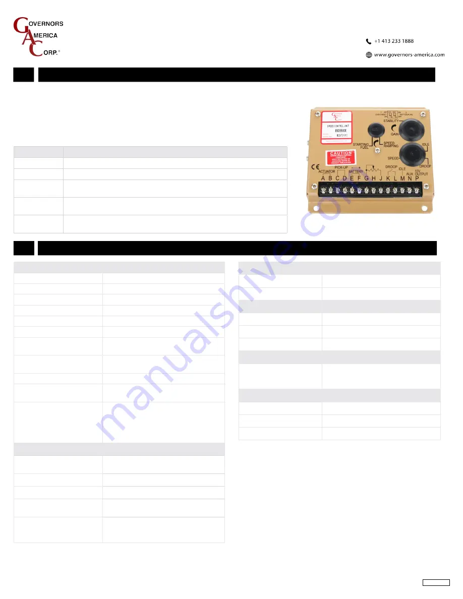
The ESD5500E Series Speed Control Unit is an all-electronic device designed to control
engine speed quickly and precisely in response to transient load changes.
The ESD5500E controls a wide variety of engines in isochronous or droop mode when
connected to a proportional electric actuator and magnetic speed sensor. The ruggedly
built ESD5500E series is designed to withstand the engine environment. Light-Force
variations are available.
moDeL
DeScrIPtIon
ESD5500E
Multi-VDC / Standard Unit
ESD5520E
Multi-VDC / Light-Force (Low-Current Optimized PID) / Enhanced Droop
ESD5522E
Multi-VDC / Light-Force (Low-Current Optimized PID) / Enhanced Droop
for Cummins EFC Forward Acting (Normally Closed)
ESD5526E
Multi-VDC / Light-Force (Low-Current Optimized PID) / Anti-Windup
Circuit (Gaseous) / Recommended for T1/T2 ATBs
ESD5528E
Multi-VDC / Anti-Windup Circuit (Gaseous) / Recommended for T3/T4
ATBs
reLIaBILItY
Vibration
1 g @ 20-100 Hz
Testing
100 % Functionally Tested
envIronmentaL
Ambient Temperature
-40° to 85 °C (-40° to 180 °F)
Relative Humidity
up to 95 %
All Surface Finishes
Fungus Proof, Corrosion Resistant
comPLIance / StanDarDS
Agency
CE (EN55011, EN50081-2, EN50082-2),
RoHS, Lloyds Register,
DNV/GL, Bureau Veritas
PHYSIcaL
Dimension
See Wiring Diagram and Outline
Weight
1.20 lbf (0.54 kgf)
Mounting
Any position, vertical preferred
* Protected against short circuit to actuator (shuts off current to actuator), unit automatically turns on when short is removed.
** Protected against reverse voltage by a series diode. A 15 A fuse must be installed in the positive battery lead.


