background image

20

LI0083 – Revision 22 June 2017


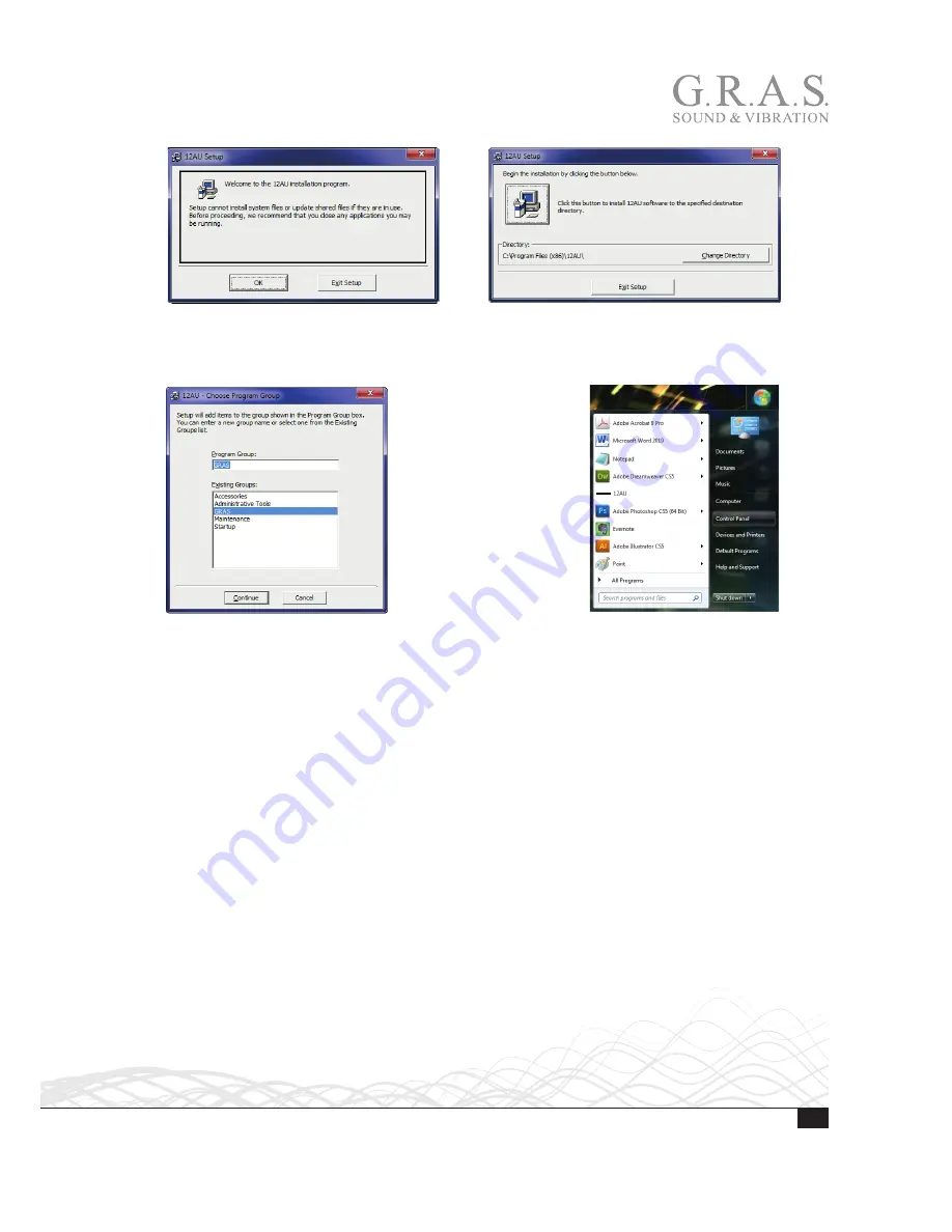
1.  Click 

OK

 (left) , then click the 

Installation button

 (right).

When the installation is complete, the control software will be selectable in the program list as 
12AU. Once installed, you can drag and drop a shortcut icon from the Windows program list to 
your desktop.

If the control software does not appear in your program list, you can find it in the folder in which it 
has been installed. In the example above, that folder is GRAS.

You can operate the 12AU using its graphical interface and a mouse. How to do this is described 
in “Using the Graphical User Interface” on page 23. Alternatively, you can enter commands in 
the 

View Log

 window. How to do this is described in “Operating the 12AU Using Commands” on 

page 28.

Summary of Contents for 12AU

Page 1: ...www gras dk LI0083 Revision 22 June 2017 Instruction Manual 12AU 1 Channel Power Module with Signal Conditioning and Power Amplifier ...

Page 2: ... amplifier output voltage swing changed to 13 5 V Copyright Notice 2012 17 G R A S Sound Vibration A S http www gras dk Any technical documentation that is made available by G R A S is the copyrighted work of G R A S and is owned by G R A S The content in this document is subject to change without notice G R A S Sound Vibration A S is not liable or responsible for any errors or inaccuracies that m...

Page 3: ...ware 18 Installing the USB Driver 18 Installing the Control Software 19 Preparing the 12AU for Measurements 21 Cables and Connections 21 Multi channel Measurements 22 Operating the 12AU via its PC Application 23 Using the Graphical User Interface 23 The Setup Menu 24 The Tools Menu 24 The Help Menu 28 Operating the 12AU Using Commands 28 Dealing with Overload in a Production Setup 29 Overload Caus...

Page 4: ...o operate the 12AU typing commands in its View Log window see Operating the 12AU Using Commands on page 28 It is optimized for computerized production line testing Up to six 12AUs can be connected to and operated from the same PC Features Single channel conditioning amplifier for microphone preamplifier and speaker amplifier with measurement of current output Controls the paths of the outgoing and...

Page 5: ...scil loscopes etc The output is floating 2 kΩ 100 nF to common ground The output impedance is 100 Ω Input for Externally Polarized Microphone or Pre polarized Microphone CCP The 12AU has a 7 pin LEMO socket for a microphone with a LEMO type preamplifier and a BNC socket for a CCP microphone set The polarization voltage can be set to 200 V or 0 V a green LED on the front indicates the currently sel...

Page 6: ... connector is a standard BNC socket floating with 10 kΩ 100 nF to common ground The input impedance is 10 kΩ The speaker amplifier has two outputs a voltage output and a current output The voltage output connector is a 2 pin LEMO pin 1 is output pin 2 is return The current output connector remote controlled is a BNC socket floating with 2 kΩ 100 nF to common ground Gain The gain can be set in step...

Page 7: ...o show that the 12AU is working properly After approximately 10 seconds it switches to operational mode Selections are made via the USB connection on the rear panel using the accompanying control software The Monitor Section The Monitor function of the 12AU makes it possible to monitor the input and output signals via separate sockets one on the front and another on the back M i c O u t A m p I n ...

Page 8: ... 1 0 d B Gain LEDs Indicates current gain setting Gain settings are from 0 dB to 50 dB in 10 dB steps Input Overload LED Lit when microphone signal overloads the 12AU Overloads can be latched and read via the USB interface in which case they are cleared when read Alternatively overload messages can be signalled to remote con trol displayed briefly and cleared automati cally High Pass 20Hz LED Lit ...

Page 9: ...settings are from 20 dB to 10 dB in 10 dB steps AC Coupled Lit when output is AC coupled When not lit the output is DC coupled Current Gain LED The LED indicates the actual current gain setting 0 dB or 20 dB Current overload LED Lit when current output goes into overload Overloads can be latched and read via the USB inter face in which case they are cleared when read Alternatively overload message...

Page 10: ...fier Input BNC input socket for signal to the speaker amplifier for example from a signal generator Input impedance is 10kΩ Current Output BNC output socket for a voltage signal proportional to the current through the output circuit of the speaker amplifier Amplifier Output 2 pin LEMO connector for a loudspeaker with an impedance of 2 Ω or more USB and Microphone Sockets Amplifier Output Current O...

Page 11: ...ions 12AU Startup Sequence After power on or restart the 12AU immediately initializes the settings of 12AU to current default settings and turns on all LEDs If connected to PC the OVL leds will be turned off when then USB connection is established typically after 4 seconds from power on Appoximate after 8 seconds the IRQ and overload system is enabled the LED will reflect the setting and a Reset c...

Page 12: ...Polarization Voltage P200 cr set polarization voltage to 200 V P0 cr set polarization voltage to 0 V High Pass Filtering HP1 cr set the conditioning amplifier high pass filter to 1 Hz HP20 cr set the conditioning amplifier high pass filter to 20 Hz HP20L cr set the conditioning amplifier high pass filter to 20 Hz with gain applied late in the chain Overload Handling LATCH cr set the conditioning a...

Page 13: ... AC couples speaker amplifier HP 10 Hz Overload Latching SLATCH cr set the speaker amplifier to latch overloads overload s are latched and cleared when read No overload messages will be sent Gain CG0 cr set the speaker amplifier gain to 0 dB CG20 cr set the speaker amplifier gain to 20 dB Current Overload Latching CLATCH cr set the speaker amplifier to latch current overloads Overload s are latche...

Page 14: ...verload status and returns OVL_on crlf or OVL_off crlf Latched overloads will be reset by reading the status SMSG cr set the speaker amplifier to submit an overload message when its voltages overload status changes returns actual overload status SOVL_on crlf or SOVL_off crlf overload is not latched SOVL cr reads overload status and returns SOVL_on crlf or SOVL_off crlf Latched overloads will be re...

Page 15: ...ns Speaker enabled or Speaker muted CG cr returns current Gain 0dB or 20dB HP cr returns Conditioning filter 0 7Hz 20Hz or 20Hz late gain SHP cr returns Speaker filter 0Hz or 10Hz Monitor cr returns selected monitor Conditioning Speaker in Speaker out or Current Name cr returns User selected name of the unit Name text saves the text in 12AU as a user selected name of the unit the USB connection is...

Page 16: ...ubmitted when MOVL is acquired or in message mode when Monitor rear output overload status changes It reflects the overload status MOVL_off crlf see MOVL_on crlf Overload Response in Latch Mode For each of the overload detectors an internal overload status flag is reflecting the actual over load condition The overload status flag will be set when an overload occurs In latch mode the status flag an...

Page 17: ...AU the overload status will not be read and no response sent back until the command has been processed Restart and Default Restart cr Restarts 12AU Factory_default cr Loads factory default values Load_default cr Loads current default values Save_default cr Saves current setup values as default the USB connection is disabled during this and 12AU restarts when ready Default Settings The conditioning...

Page 18: ...e USB Driver Prior to connecting the 12AU you must install the dedicated USB device driver on the PC that you will use to operate the 12AU Important The installation requires that you are logged in as administrator on the PC 1 Insert the 12AU USB stick delivered with the 12AU in your PC 2 In Windows Pathfinder open the 12AU Installation USB 3 Open the usb_driver directory containing the USB driver...

Page 19: ...tion must be set to 1024 x 768 or higher Important The installation requires that you are logged in as administrator on the PC Requirements Operating system Windows XP Windows Vista or Windows 7 Screen resolution 1024 x 768 or higher A mouse or other suitable pointing device USB port Installation 1 Insert the Control software USB stick for 12AU in your computer 2 Run setup from the root of the ins...

Page 20: ...ram list to your desktop If the control software does not appear in your program list you can find it in the folder in which it has been installed In the example above that folder is GRAS You can operate the 12AU using its graphical interface and a mouse How to do this is described in Using the Graphical User Interface on page 23 Alternatively you can enter commands in the View Log window How to d...

Page 21: ... up by the microphone is fed to the analyzer via a BNC cable For comparison these signals can be monitored separately during the measurement Connection is via BNC and the monitoring is software controlled M ic O u t A m p In A m p O u t C u rr e n t O u t 2 0 d B 3 0 d B 4 0 d B 5 0 d B Monitor Microphone Conditioner O v e rl o a d H ig h P a s s 2 0 0 V o lt C C P 2 0 d B 1 0 d B 0 d B 1 0 d B O ...

Page 22: ...C via USB You can launch a separate instance of the control software for each 12AU connected to the PC The control software will automatically look for a 12AU and lock to its serial number Each 12AU can be given a name assigned an identification making it easy to separate it from other 12AUs controlled from the same PC For information about how to do this see Save Settings as Default in 12AU on pa...

Page 23: ... Fig 5 is displayed Fig 5 The 12AU User Interface The 12AUs graphical user interface resembles the front panel You can operate the 12AU using the pull down menus and by clicking the LEDs representing the settings of the sections of the 12AU Selecting Settings 1 Change a setting by clicking the LED symbol below the setting in question The LEDs will turn green or get dimmed to confirm your choice Al...

Page 24: ...you can Activate the View log window in which you can monitor the communication between the control application and the 12AU See View Log on page 25 View amplifier temperature See View Temperature on page 25 Enlarge the graphical user interface See Enlarge the Graphical User Interface on page 25 Select Enable advanced allowing you to assign a name to 12 AU See Assign a Name on page 26 save actual ...

Page 25: ...AU log here showing the default settings after power up View Temperature In the Tools menu you can enable monitoring of the amplifier temperature View amplifier temperature The actual temperature is shown in the status bar see Fig 10 Fig 10 12AU with View amplifier temperature enabled Enlarge the Graphical User Interface In the Tools menu you can select to Enlarge the graphical user interface The ...

Page 26: ...r Fig 12 The Advanced password pop up window To access this function you need to enter the password gRas in the Advanced password pop up window This password is hard coded into the firmware and cannot be changed You must type it exactly as shown here 2 Type gRas and press Enter The name field shown in the status bar appears see Fig 13 Assign a Name When you have entered the password you can give t...

Page 27: ...ccess the other Enable advanced functions you need to proceed as described in Enable Advanced on page 26 Save Settings as Default in 12AU It is possible to store the actual settings as default setup in the 12AU This feature makes it possible for the 12AU to start up in a user defined setting independently of the control software and the communica tions link to the PC Fig 17 When Enable advanced is...

Page 28: ...perate the 12AU in command mode you must first Enable advanced in the Tools menu and then enter the password as described on page 26 Proceed as follows 1 Click on the Tools menu 2 Select Enable advanced 3 Type the password in the Advanced password window 4 Select View log to display the Type 12AU Log window 5 In the Tools menu of the G R A S Type 12AU log window select Command mode The graphical u...

Page 29: ...reduces the overload The HP20L filter setting applies most of the gain at the output amplifier e g 30 dB will be achieved with 10 dB at the input and 20 dB at the output Normally the most gain will be applied at the input amplifier to achieve best signal to noise ratio Input Output Overload detection Overload detection HP 1 HZ 20 HZ 1 order HP 1 HZ 20 HZ 2 order Gain in dB 30 20 10 0 Gain in dB 20...

Page 30: ...the 12AU to tour PC before installing the USB driver the installation software cannot install the driver To circumvent this problem you need to update the driver using the Windows Device Manager from the Windows Control Panel 1 Open the Control Panel in the Windows Start menu 2 Select Hardware and Sound 3 Select Device Manager The 12AU will be listed under Other Devices ...

Page 31: ...n 22 June 2017 4 Right click CDC RS 232 Emulation GRAS and select Properties 5 Select the tab General and click the Update Driver button 6 Click Browse my computer for driver software to access the 12AU installation USB ...

Page 32: ...ne 2017 7 Select usb_driver on the Installation USB 8 Ignore the authenticity warning The USB driver will now be updated with the Microtech USB driver required by the 12AU The installation is complete when confirmed by Windows ...

Page 33: ...mpedance 100 Ω Gain 0 50 dB in 10 dB steps 0 2 dB remote controlled Bandwidth 3 dB 1 Hz 100 kHz Noise floor relative to input Input shorted 20 dB gain Input loaded with 20 pF dummy mic 1 5 μVrms 20 Hz 20 kHz 5 μVrms 20 Hz 20 kHz High pass filter remote controlled 1 order Butterworth 3 order 1 Hz 20 Hz Overload detection LED indicators remote controlled Speaker amplifier section Amplifier Input con...

Page 34: ...correct power supply or an incorrect connection to the equipment Service and Repairs All repairs are made at G R A S International Support Center located in Denmark Our Support Center is equipped with the newest test equipment and staffed with dedicated and highly skilled engineers Upon request we make cost estimates based on fixed repair categories If a product covered by warranty is sent for ser...

Reviews: