


Section 10
00-02-0511
2019-07-10
7
Setup (continued)_________________________________________________
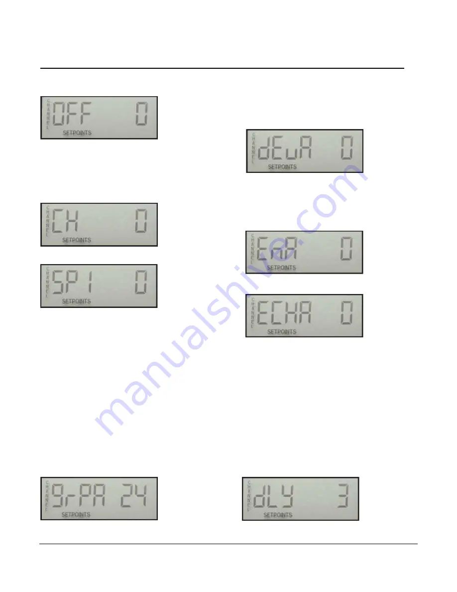
Use the UP and DOWN buttons to select the desired channel to
set up. (Select CH 0 to exit.) Press SCROLL ENTER, and the
LCD will read:
Use the UP and DOWN buttons to adjust the offset for the
channel being set. Press the SCROLL ENTER button to go back
to the channel display. Go to CH 0 to exit by pressing SCROLL
ENTER. Press the UP button to go to SETUP 3.
Setup 3 SETPOINTS
Press the SCROLL ENTER button to get into the setpoint setup.
The LCD will first display the Channel Select entrance/exit
display:
Use the UP and DOWN buttons to select the desired channel to
setup. Press the SCROLL ENTER button and the LCD will read:
SP# indicates the output that the setpoint is tied to. For example,
SP 1 is tied to Output 1 (SP1 OUT). Use the UP and DOWN
buttons to set the desired set point. Press the SCROLL ENTER
button to accept the entry. Repeat for SP2 and SP3, and you will
return to the Channel Select display. Repeat until all set points
are entered.
Note that entering Ø (zero) for a setpoint will disable the output for
that particular channel. With zero as the set point, open
thermocouple will not cause that output to activate. In this way,
channels can be grouped, if desired. Further, an alarm before
shutdown feature can be implemented by setting the set points
progressively higher. For example, if SP1 = 900 and SP2 = 1000,
Output 1 (SP1 OUT) could be wired to an Alarm Input and Output
2 to a Shutdown Input on an annunciator. The range of
adjustment is 0-1999 in the Units (°F or °C) chosen for those
channels. Once all set points have been entered or checked, go
to the CH 0 entrance/exit display. Press the SCROLL ENTER
button to exit. Then press UP to go to Setup 4.
Setup 4 GRP / DEV SETUP
At the Setup 4, press the SCROLL ENTER button. The LCD will
first display the Number of Channels in the first group to Average.
All first group settings have the letter A. The second group
settings have the letter B:
If the group is set to Ø (zero), the function is disabled. The first
group must start with Channel 1. For an example on a 16
cylinder engine, group will be set to 16. The first 16 channels will
be in the group. The group can be all 24 channels. If a second
group is used, it starts with the first channel after the first group.
Use the UP
and DOWN
buttons to select the number of channels
that will be grouped in the averaging group. Enter Ø (zero) to
disable this feature. Press the SCROLL
ENTER
button. Next
enter the allowable deviation. This is a temperature adjustable
from 0
–255 in the Units (°F or °C) chosen for the channels:
If any of the grouped channels (beginning with channel 1)
deviates from the average of the other channels by the amount
entered, Output
1
will be energized. Use the UP
and DOWN
buttons to enter an amount. Press the SCROLL
ENTER
button.
Next enter the enable value. This is a temperature setpoint for
enabling the group/deviation function. If the temperature of the
channel selected in the next setting exceeds this enabled set
point, the group/deviation function becomes active:
Use UP
and DOWN
to enter a value. Press the SCROLL
ENTER
button and enter the enable channel:
If this channel value is set to Ø (zero), any of the grouped
channels will enable the group/deviation function when any of
the channels reaches the EN
value. If this channel value is set
to any other value (1-24), then ONLY that channel will enable
the deviation function when it reaches the EN
value. The
enabling channel does not have to be in the group. Use the UP
and DOWN
buttons to enter a value.
Press SCROLL
ENTER,
and the display will go to grpb for the
second group. If a second group is not desired, the grpb setting
should be set to zero. With a setting of zero. pressing scroll enter
will bring back the setup 4 display. If a second group is used, it is
done like the first group.
Setup 5 CH SCAN DELAY
At Setup 5, press SCROLL ENTER. The LCD will display the
current display delay between channels during Normal Scan. This
delay is also the update delay for the temperature readings. The
channels are still scanned within 2 seconds and trip point
comparisons are made, but the actual display of the temperature
is delayed by this time.
Summary of Contents for TDXM-DC Series
Page 4: ...THIS PAGE INTENTIONALLY LEFT BLANK...
Page 13: ...Section 10 00 02 0511 2019 07 10 9 Map of Setup...
Page 14: ...Section 10 00 02 0511 2019 07 10 10 Map of Setup continued...
Page 18: ...Section 10 00 02 0511 2019 07 10 14 Notes...
Page 19: ...Section 10 00 02 0511 2019 07 10 15 Notes...
Page 20: ......


