


Section 10
00-02-0511
2019-07-10
5
Sequence of Operations
Scanning
Normal Scan
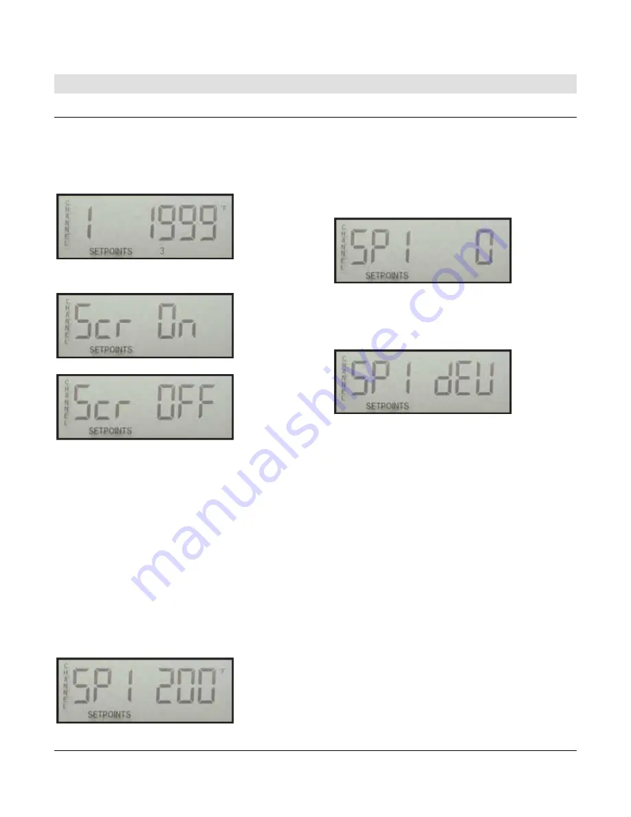
During Normal Scan mode, each channel is displayed for the
period set in the CH SCAN DELAY (Setup 5). The default is 3
seconds. When the CH SCAN DELAY expires, the display
changes to show the next channel. After all channels have been
displayed, the sequence starts again from the first channel. The
LCD looks like this:
The Normal Scan mode can be turned ON or OFF. To toggle the
Normal Scan mode, press and hold the SCROLL button until the
display shows (approx. 1 sec.).
Or
It is possible to disable channels from being displayed, by
selecting the channel as Ø=Ignored in the TC TYPE / UNITS
(Setup 1).
LOCKED SCAN
During a Locked Scan, the Normal Scan is temporarily interrupted
and only the Locked Channel is displayed for 60 seconds. A
channel is locked when the UP or DOWN buttons are used to
select a channel during Normal Scan mode. To unlock and
resume Normal Scan mode, press the SCROLL button.
After 60 seconds, the Normal Scan mode will resume, if no other
keys have been pressed.
It should be noted that while only one channel is being displayed,
all channels are being scanned and checked against their (3) set
points every 2 seconds. All set points remain active at all times.
CHANNEL SP1-3
During Normal or Locked Scan mode, the set points for each
channel can be viewed. To enter the CHANNEL SP view for the
channel currently displayed, press and hold the CHANNEL SP1-3
button for approx. 1 second.
The display will first show:
From this display, use the UP
button to view SP2
and SP3. Press
the CHANNEL
SP1
-
3
button again to return to the Normal or
Locked Scan mode. No changes can be made to the set points
from this view. To change a set point, use the SETPOINTS
(setup
3) menu.
SP HISTORY
During Normal or Locked Scan mode, a history of the last channel
setpoint trip can be viewed. To enter the SP HISTORY channel
display, press the SP HISTORY button.
The display will first show:
The value on the right represents the channel that tripped for the
SP# shown. From this display, use the UP button to view SP2 and
SP3. For each SP# it is possible to view the set point for that
channel when the channel tripped. Press the CHANNEL SP1-3
button to view the setpoint for the channel stored in the history.
If the group/deviation caused the trip, the display will show:
Pressing the CHANNEL SP1-3 button will show the channel that
caused the trip and the temperature deviation that caused the trip.
The temperature deviation shown is an absolute value. In other
words if the deviation was a negative number, a positive number
will be shown.
SP3 LATCH
The TDXM-DC W/SP3 LATCH is a special version available to
latch one of the three digital outputs when a trip is detected. For
this version only, setpoint values are first-out. If a sensor channel
temperature rises above set point, SP3 will activate and remain
active until RESET or power is recycled in the unit. The display
will show 1 2 3 (#3 is ON). The icons for SETPOINT 1 and 2 may
also be ON depending on the status of those set points.
If the tripped channel clears, the output for SP3 will not clear and
the SP History for SP3 will not be overwritten by other SP3 trips.
Example: If CH21 and CH22 have an SP3 setpoint of 180 and
CH21 temperature rises to 190, SP3 OUT will be activated, and
the SP History will show SP3 21 as the cause for trip. If
temperature for SP3 21 falls below 180 or SP3 22 rises above
180 after the trip has occurred, the SP3 OUT will remain active,
and the SP History will not be altered. All channels continue to be
scanned and compared against SP1 and SP2 setpoint values.
To RESET the SP3 Output and allow continued scanning of SP3
set points, press and hold SCROLL ENTER and DOWN ARROW
keys simultaneously for at least 3 seconds. The display will
indicate the latch has been cleared when the number 3 is no
longer visible on the SETPOINT icon display. The display will
show SETPOINT 1 2 3 (#3 is OFF). The icons for SETPOINT 1
and 2 may also be ON depending on the status of those set
points.
Summary of Contents for TDXM-DC Series
Page 4: ...THIS PAGE INTENTIONALLY LEFT BLANK...
Page 13: ...Section 10 00 02 0511 2019 07 10 9 Map of Setup...
Page 14: ...Section 10 00 02 0511 2019 07 10 10 Map of Setup continued...
Page 18: ...Section 10 00 02 0511 2019 07 10 14 Notes...
Page 19: ...Section 10 00 02 0511 2019 07 10 15 Notes...
Page 20: ......


