Section 50
00-02-1033
2018-12-03
- 6 -
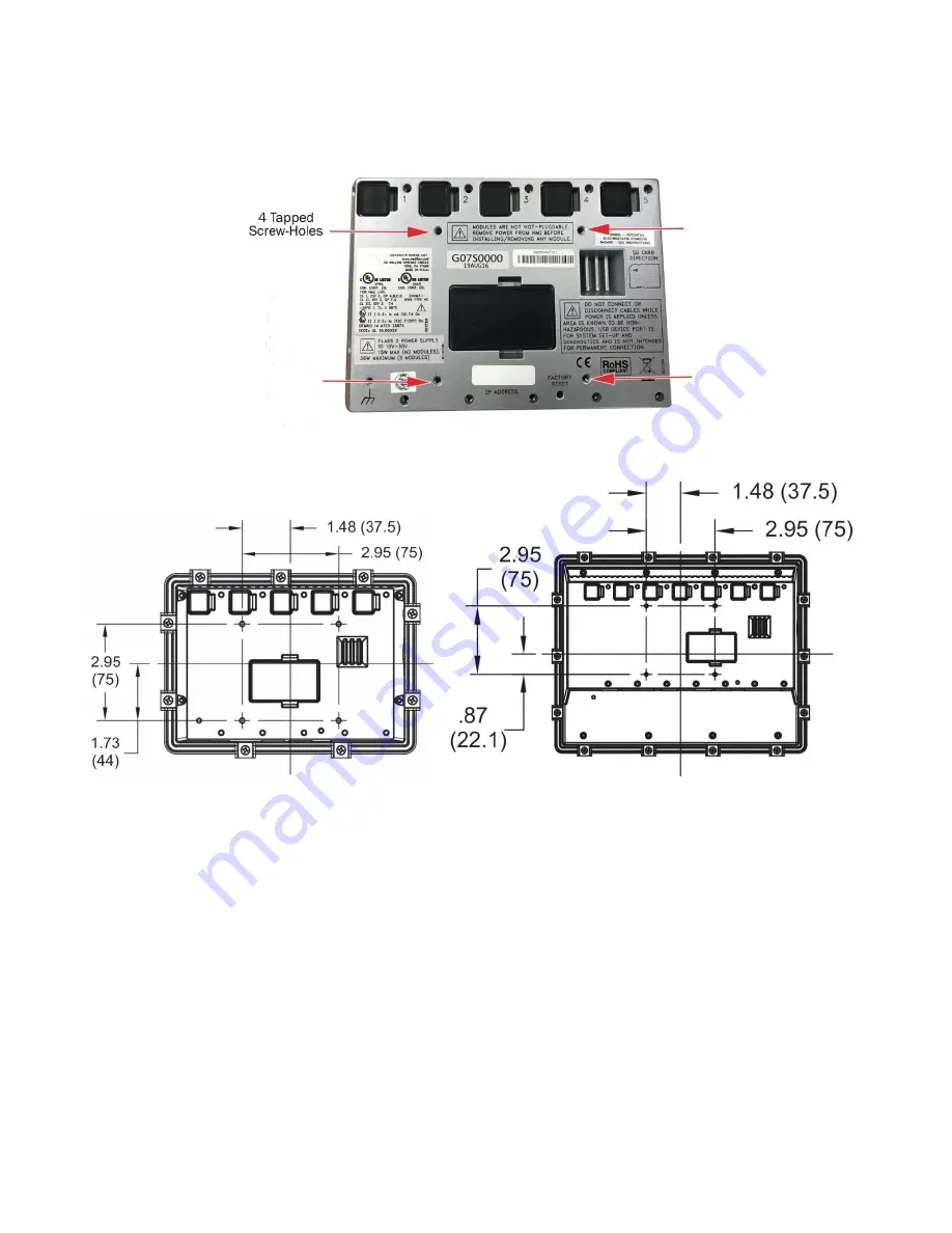
Stand Mount
Four mount-tapped screw holes (M4 x 0.7, 5 mm deep) are located on the rear of the panels for stand or wall mounting.
Tapped screw hole locations
MV-7T
MV-10T
Page 1: ...Components Include MX4 R2 Interchange Communication Control Module MX5 R2 Interchange Communication Control Module Before installing the product inspect each item for damage which sometimes occurs du...
Page 2: ...y accessible by the use of a tool Pressure 80 kPa 0 8 bar to 110 kPa 1 1 bar Air with normal oxygen content typically 21 v v Temperature Class T4 ic intrinsic safety for EPL Gc Increased safety for EP...
Page 3: ...Section 50 00 02 1033 2018 12 03 3 M VIEW Display Dimensions MV 5 C M VIEW Monochrome LCD MV 7T M VIEW Touch Series MV 10T M VIEW Touch Series...
Page 4: ...of controller in the cutout before proceeding with drilling mounting holes 5 If applicable drill holes where indicated for the mounting screws MV 5 C Display NOTE The Centurion MV 5 C display can be...
Page 5: ...rt the display back side first from the front side of the panel 3 Ensure that there is adequate clearance for the edges of the display housing and the back of the case is flush against the outside sur...
Page 6: ...ection 50 00 02 1033 2018 12 03 6 Stand Mount Four mount tapped screw holes M4 x 0 7 5 mm deep are located on the rear of the panels for stand or wall mounting Tapped screw hole locations MV 7T MV 10T...
Page 7: ...r User Menu in addition to the Standard password features Default passwords are Operator 164 Super User 133 Your password access times out three minutes after the editing session is exited NOTE If a p...
Page 8: ...nd verify its drawing number matches the sticker on the lower front panel 2 Locate the legend of the drawing and find the configuration description Record this description 3 Power up the Centurion Sys...
Page 9: ...tatus MVIEW Comm Status Centurion Comm Status Real Time Clock Setup Super User Setup Centurion Serial Ports Centurion Can Ports Centurion Ethernet Centurion EMMC Log MVIEW Serial Ports MVIEW CAN Ports...
Page 10: ...the Unit State will read Stopping 4 When everything has been recognized as back to normal the Unit State will read Panel Ready Fault Shutdown The Centurion will continually monitor for Fault or ESD sh...
Page 11: ...be displayed as a percentage of the range d Custom Generic Register allows user to display up to 20 items on a page that can be mapped to the Centurion Modbus map and given a label For more informati...
Page 12: ...en approximately 15 seconds b If Centurion has integrated EICS displays enabled the System View will be the initial powerup view Touch the screen on the Centurion Gage side to open its Home screen in...
Page 13: ...n icon to view information about the items and settings available on the displayed page 5 Start the unit a Clear any Alarms Class A always armed faults from the system On the display the Unit State wi...
Page 14: ...een with time and date of occurrence 1 The Shutdown History screen displays information of the fault Touch the Book icon for troubleshooting a Centurion Home Gage Screen FN Shutdown History 2 The Shut...
Page 15: ...rcentage of the range d Custom Generic Register allows user to display up to 20 items on a page that can be mapped to the Centurion Modbus map and given a label For more information on configuring the...
Page 16: ......