FW Murphy Centurion C5 Quick Start Manual Download Page 4

Section 50 


00-02-1033 

2018-12-03 

- 4 - 

Install the Display 

Prepare the Panel 

– All M-VIEW Models 

The suitability of the enclosure is subject to investigation by the local authority having jurisdiction at the time of the 
installation. 

1.  Determine the location of the display on the customer-supplied flat or enclosed panel. Plan the display 

mounting for easy wiring and access. 

2.  Measure the specified dimensions shown in the diagram of the screen side. Doing so will ensure there is 

adequate real estate to provide clearance for the front edges of the housing to mount flush against the 
outside surface of your panel. The cut-out measurement will be smaller. 

3.  Use the diagram to measure and mark the specified dimensions shown in the panel cut-out diagram. This 

is your cut-out measurement. 

4.  Cut the hole in the panel following your marks matching the diagram as a guideline.  

NOTE:

 Check for clearance fit of controller in the cutout before proceeding with drilling 

mounting holes. 

5.  If applicable, drill holes where indicated for the mounting screws. 
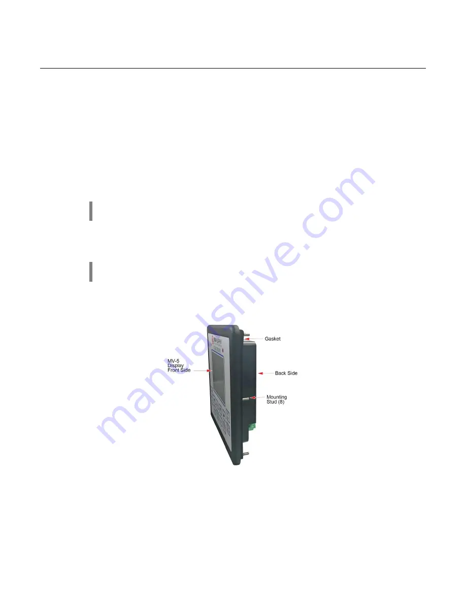
MV-5-C Display 

NOTE:

 The Centurion MV-5-C display can be mounted in the same fastener hole cutouts 

as the Centurion C4 display. 

1.  Inspect the gasket on the back side of the display making sure 

it’s secured to the display and aligned with 

the mounting studs. 

2.  Insert the MV-5-C display back side first, from the front side of the panel.  


3.  Ensure there is adequate clearance for the edges of the display housing and the back of the case is flush 

against the outside surface of your panel. 

4.  If thread lock is desired for your application, apply blue polycarbonate compatible thread lock to the 

threads of the mounting studs. It is not a requirement of installing Centurion C5.  

5.  Install the locknuts to each mounting stud from the back side of the panel to secure the MV-5-C housing.  

6.  Use an x-pattern to evenly tighten the locknuts to 8 in. lbs. (0.9 Nm). Do not overtighten. 

7.  Ensure there is a good seal between the controller, the gasket and the mounting panel.


Summary of Contents for Centurion C5

Page 1: ...Components Include MX4 R2 Interchange Communication Control Module MX5 R2 Interchange Communication Control Module Before installing the product inspect each item for damage which sometimes occurs du...

Page 2: ...y accessible by the use of a tool Pressure 80 kPa 0 8 bar to 110 kPa 1 1 bar Air with normal oxygen content typically 21 v v Temperature Class T4 ic intrinsic safety for EPL Gc Increased safety for EP...

Page 3: ...Section 50 00 02 1033 2018 12 03 3 M VIEW Display Dimensions MV 5 C M VIEW Monochrome LCD MV 7T M VIEW Touch Series MV 10T M VIEW Touch Series...

Page 4: ...of controller in the cutout before proceeding with drilling mounting holes 5 If applicable drill holes where indicated for the mounting screws MV 5 C Display NOTE The Centurion MV 5 C display can be...

Page 5: ...rt the display back side first from the front side of the panel 3 Ensure that there is adequate clearance for the edges of the display housing and the back of the case is flush against the outside sur...

Page 6: ...ection 50 00 02 1033 2018 12 03 6 Stand Mount Four mount tapped screw holes M4 x 0 7 5 mm deep are located on the rear of the panels for stand or wall mounting Tapped screw hole locations MV 7T MV 10T...

Page 7: ...r User Menu in addition to the Standard password features Default passwords are Operator 164 Super User 133 Your password access times out three minutes after the editing session is exited NOTE If a p...

Page 8: ...nd verify its drawing number matches the sticker on the lower front panel 2 Locate the legend of the drawing and find the configuration description Record this description 3 Power up the Centurion Sys...

Page 9: ...tatus MVIEW Comm Status Centurion Comm Status Real Time Clock Setup Super User Setup Centurion Serial Ports Centurion Can Ports Centurion Ethernet Centurion EMMC Log MVIEW Serial Ports MVIEW CAN Ports...

Page 10: ...the Unit State will read Stopping 4 When everything has been recognized as back to normal the Unit State will read Panel Ready Fault Shutdown The Centurion will continually monitor for Fault or ESD sh...

Page 11: ...be displayed as a percentage of the range d Custom Generic Register allows user to display up to 20 items on a page that can be mapped to the Centurion Modbus map and given a label For more informati...

Page 12: ...en approximately 15 seconds b If Centurion has integrated EICS displays enabled the System View will be the initial powerup view Touch the screen on the Centurion Gage side to open its Home screen in...

Page 13: ...n icon to view information about the items and settings available on the displayed page 5 Start the unit a Clear any Alarms Class A always armed faults from the system On the display the Unit State wi...

Page 14: ...een with time and date of occurrence 1 The Shutdown History screen displays information of the fault Touch the Book icon for troubleshooting a Centurion Home Gage Screen FN Shutdown History 2 The Shut...

Page 15: ...rcentage of the range d Custom Generic Register allows user to display up to 20 items on a page that can be mapped to the Centurion Modbus map and given a label For more information on configuring the...

Page 16: ......

Reviews: