.
Page 21
11/16/01
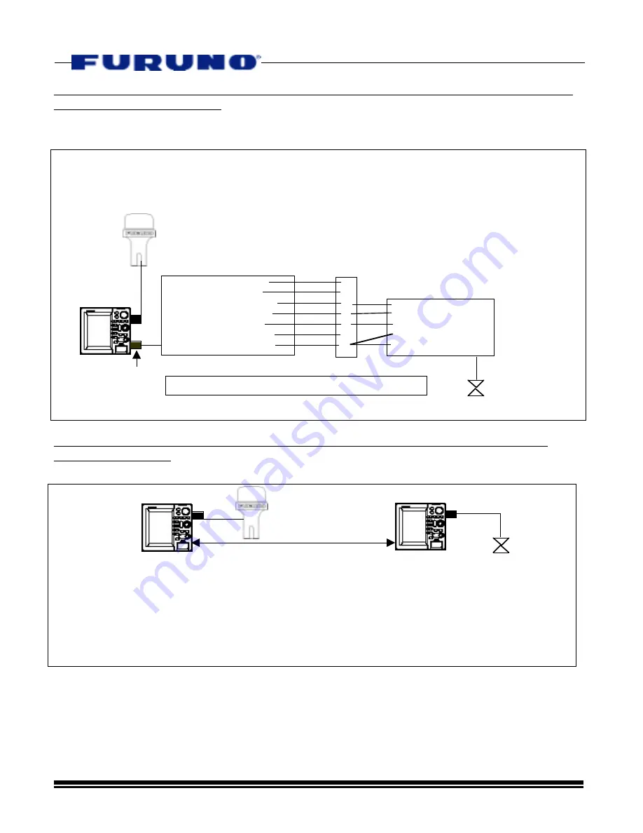
Smart Sensor Installation Example #2 – Modifying or Cutting the Smart Sensor Cable for
Connection to DATA3/DATA4
This method utilizes the existing Smart Sensor 7 pin connector or a 000-144-418 cable to
allow connection to the DATA3/DATA4 7 pin connector.
Smart Sensor Installation Example #3 – Multiple NavNet Display Configuration Using
DATA1 Connections
DATA1
DATA1
Smart Sensor
Network
GP-310B or Other
Position Source
-In this case, Smart Sensor can be connected directly to the DATA1 port on another NavNet
Display. NOTE: Both displays must be turned on in order to share position and
depth/temperature data. Multiple Displays may also be connected in this way.
-YOU MUST follow the procedure from Section “D” above to output the proper Temp. and Depth
Data to other NavNet Displays in the Network. Follow the same procedure and turn on “MTW”
and “DPT” at the NavNet Display that is connected to the Smart Sensor.
1
2
3
4
5
6
7
WHITE NMEA(+)
BLUE NMEA(-)
RED +12VDC
BLACK GROUND
SHIELD
Smart Sensor Cable
Terminal Strip
DATA1
GP-310B or
other Pos.
Source to
DATA1
Smart Sensor
DATA3/DATA4
1. TD(+)RS232 WHITE*
2. RD(-)RS232 BLUE
3. RD-A Input YELLOW
4. RD-B Input GREEN
5. +12V DC
RED
6. Buzzer Out - BLACK
7. SHIELD/GND BARE*
000-144-418 7-Pin
Cable to Buzz/
RS232/NMEA In
12VDC Port”
The existing Smart Sensor Connector may also be used
for connection to DATA3/DATA4 instead of the 000-144-
418 Cable. However, there is no way to provide
NMEA0183 Output to other equipment. To do this the
Black Wire in the Smart Sensor cable must be cut.
Then, the Black Wire lead going to the sensor must be
spliced together with the shield. See the diagram
directly below.
*Use White(+)/Bare(-) to Provide NMEA0183 Output


