background image

1.  OPERATION

1-3

How to turn the system on

To turn the system on, press the power button. After pressing the power button, the 
LED on the main PC lights up and the system begins its startup process. When the 
startup process is completed, the following message appears. Confirm the message, 
then click the [OK] button to close the message.

When connecting to the IP camera, the following message appears at the center of 
the screen. Connecting process can take up to approximately one minute. After con-
necting with the IP camera, the AR navigation system screen appears automatically 
on the display.

Note: 

When the user chart file has be imported, the message 

shown in the figure to the right appears. For how to import the 
user chart file, see subsection 1.9.1.

How to turn the system off

To turn the system off, press the power button again.

1.4

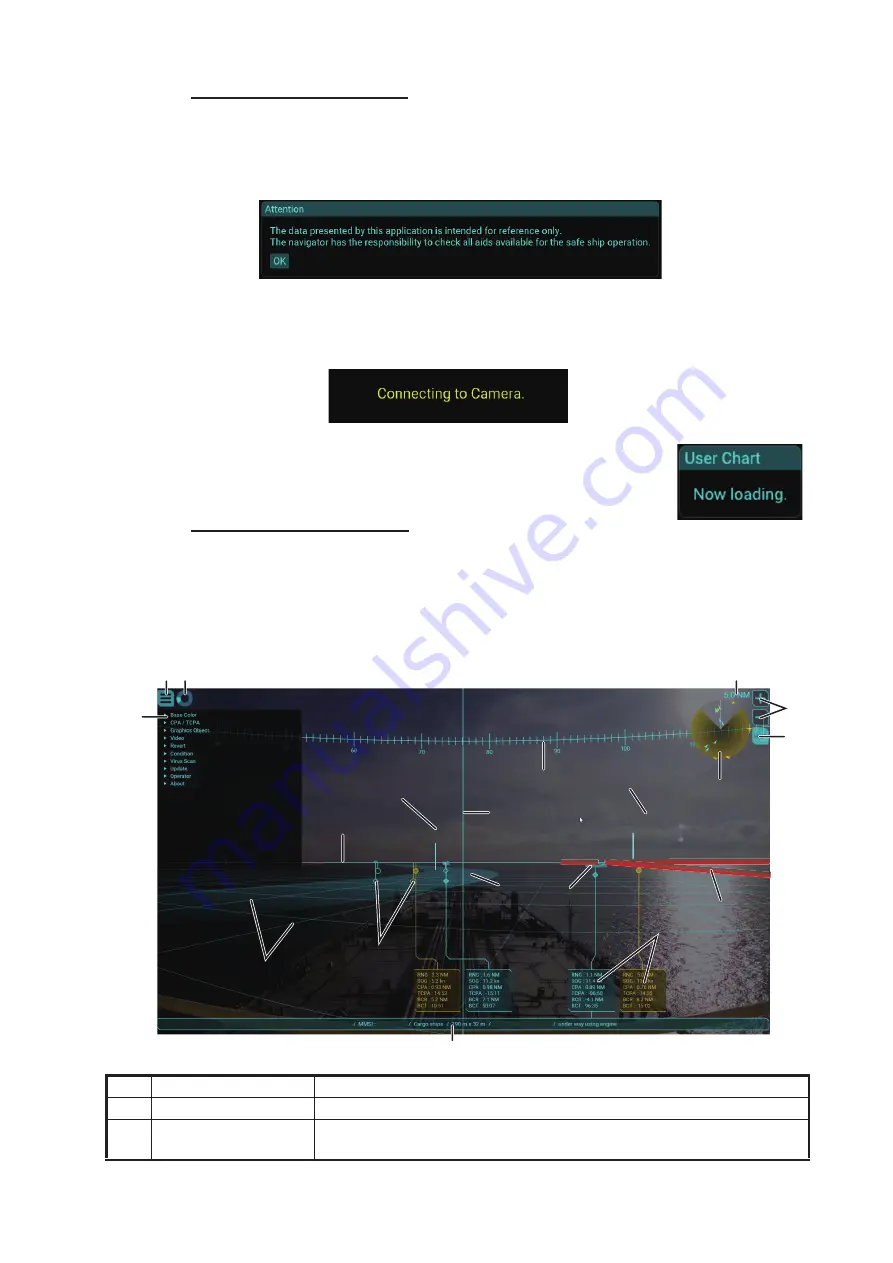
Display Overview

No.

Name

Description

1

Menu button

Opens/closes the main menu.

2

Working indicator

Rotates clockwise when the system is working correctly. Stops rotat-
ing when the system is frozen or malfunctioning.

1 2

4

5
6

77

88

99

1.5NM

10:45

71.3°

11

11

12

12

XXXXXXX 3.0NM

13

13

14

14

15

15

10

10

3

17

17

18

18

16

16

19

19

FURUNO

FURUNO

XXXXXXXXX

Summary of Contents for ENVISION AR-100M

Page 1: ...AR NAVIGATION SYSTEM AR 100M OPERATOR S MANUAL www furuno com Model ...

Page 2: ...7KH SDSHU XVHG LQ WKLV PDQXDO LV HOHPHQWDO FKORULQH IUHH 85812 XWKRUL HG LVWULEXWRU HDOHU VKLKDUD FKR 1LVKLQRPL D 3 1 6 3 3ULQWHG LQ DSDQ OO ULJKWV UHVHUYHG 3XE 1R 20 5 8 5 0 ...

Page 3: ...ndows is either registered trademarks or trademarks of Microsoft Corporation in the United States and or other countries How to discard this product Discard this product according to local regulations for the disposal of industrial waste For disposal in the USA see the homepage of the Electronics Industries Alliance http www eiae org for the correct method of disposal How to discard a used battery...

Page 4: ...wer off before beginning the installation Be sure both the system and all external devices are turned off Sudden surge of power could damage the equipment The operator and installer must read the applicable safety instructions before attempting to operate or install the equipment Do not disassemble or modify the equipment Fire electrical shock or serious injury can occur Turn the power off immedia...

Page 5: ...rts created on the ECDIS 1 14 1 9 2 How to show hide the user charts 1 16 1 9 3 How to adjust area object transparency 1 16 1 9 4 How to customize no go area objects 1 16 1 9 5 How to adjust the text size for label objects 1 17 1 10 How to Adjust the Video Image Brilliance 1 17 1 11 How to Adjust the Video Image Position 1 18 2 INSTALLATION AND INITIAL SETTINGS 2 1 2 1 Mounting 2 1 2 1 1 Main PC 2...

Page 6: ...System Information 3 8 3 7 1 How to show the system information 3 8 3 7 2 Sentence monitor window 3 9 3 8 How to Perform the Virus Scan 3 10 3 9 How to Update the AR Navigation System Application 3 11 3 10 How to Update Virus Definition 3 12 3 11 How to Update the Operating System 3 14 3 12 How to Show Software Information 3 15 APPENDIX 1 MENU TREE AP 1 SPECIFICATIONS SP 1 PACKING LISTS A 1 INTERC...

Page 7: ...u the end user about whether we are achieving our goal Thank you for considering and purchasing FURUNO equipment Cyber Security Notes Keep in mind the following points to protect the AR navigation system from viruses The AR navigation system is equipped with anti virus software The virus definitions and related files must be kept up to date The operator is solely responsible for updating the virus...

Page 8: ...pment Monitor 100 240 VAC Main PC PoE Adapter IP Camera Standard supply Local supply Trackball Intelligent HUB HUB 3000 100 230 VAC 1Ø 50 60Hz ECDIS FMD 3200 3300 Radar FAR 3000 FAR 2 7 FAR 2 8 Radar Sensor Antenna Unit Satellite Speed Log GS 100 or SATELLITE COMPASSTM SC 33 SC 70 SC 130 Gyrocompass GPS GP 150 GP 170 AIS FA 150 FA 170 100 240 VAC ...

Page 9: ...le DH HD14E50 RS 000 197 075 10 1 10 m cable between main PC and monitor LAN Cable P5E 4PTX BL L 10M 000 164 637 10 2 10 m cable between HUB 3000 and main PC IP camera and PoE adapter P5E 4PTX BL L 2M 000 164 634 10 1 2 m cable between PoE adapt er and main PC USB Cable KU EN5K 000 197 073 10 2 5 m cable between USB flash memory and main PC Trackball and main PC Bracket TB 109 000 197 072 10 1 For...

Page 10: ...EQUIPMENT LIST viii This page is intentionally left blank ...

Page 11: ...hart symbols from ECDIS FURUNO FMD 3200 3300 The system keeps the AR objects aligned with the actual targets compensating for roll pitch and yaw Note 1 Do not solely rely on the AR navigation system to navigate the vessel Always check your position against all available aids to navigation for the safety of vessel and crew Note 2 An ENC dongle is necessary to share the ENC charts from the ECDIS The...

Page 12: ...en you turn the system on off keep in mind the following points Supply power to the IP camera BEFORE turning on the AR navigation system The video image may not appear if the IP camera is not powered first If the video image does not appear restart the AR navigation system Lightly press the power button If the power button is pressed too firmly the button may get caught on the chassis Do not turn ...

Page 13: ...ting with the IP camera the AR navigation system screen appears automatically on the display Note When the user chart file has be imported the message shown in the figure to the right appears For how to import the user chart file see subsection 1 9 1 How to turn the system off To turn the system off press the power button again 1 4 Display Overview No Name Description 1 Menu button Opens closes th...

Page 14: ...e heading guide intersects the azimuth scale Note When the IP camera position is offset from the ship s center the heading guide is not aligned with the ship s bow on the video image 10 Horizon line Indicates the horizon and is used to adjust the video image position Normally hide the horizon line For how to show hide the horizon line see subsection 1 8 3 11 Waypoint information Display the inform...

Page 15: ...ctive marker To close the frame click the selective marker again to dese lect the marker You can customize the information to be shown in the frame See subsection 1 8 6 18 Appended target in formation frame Click the main target information frame to show the appended target information frame To close the frame click the main target informa tion frame again You can customize the information to be s...

Page 16: ...VI Note 1 The normal target color depends on the base color setting See section 1 6 Note 2 The attentional target color can be changed from the menu See section 1 7 1 6 How to Change the Base Color You can change the base color for the AR navigation system screen The base color is applied to the following items 1 Click the menu button to open the main menu 2 Click Base Color 3 Click an appropriate...

Page 17: ...t the slider bar for TCPA Threshold to change the TCPA threshold 5 Click an appropriate checkbox of Attentional Color to select the color for the at tentional target 6 Close the main menu 1 8 How to Customize the Graphics Object 1 8 1 How to show hide the azimuth scale The azimuth scale is shown at the top of the screen You can use the scale to estimate the bearing of ship s heading or a target Th...

Page 18: ...se the main menu 1 8 3 How to show hide the horizon line You can show the horizon line on the AR navigation system If the horizon line is not aligned with the horizon on the screen adjust the position of the video image See section 1 11 Note The horizon line is used to adjust the video image position Normally hide the horizon line 1 Click the menu button to open the main menu 2 Click Graphics Obje...

Page 19: ...t 3 Click Grid 4 Check the checkbox for Visible to show the grid If you want to hide the grid remove the check mark from the checkbox 5 Check the radio button for World or Own 6 Adjust the slider bar for Pitch Extension and Density as appropriate Pitch Adjust the pitch for the grid lines Extension Adjust the number of the grid cells Density Adjust the transparency of the grid lines 7 Close the mai...

Page 20: ...heck mark from the checkbox 5 Close the main menu 1 8 6 How to customize target information You can customize the contents in the main target information frame and appended target information frame 1 Click the menu button to open the main menu 2 Click Graphics Object 3 Click Target Information Buoy Virtual buoy AIS target boat AIS target tanker Main target information frame Main target information...

Page 21: ... other set ting box 5 Order change button Changes the order of the data selected with the cur sor Item Description NAME Vessel name For targets whose vessel name data is not available No Name appears ID TT target When the data source can be specified radar ID and target ID are shown AIS target MMSI is shown SIZE Vessel size of the AIS target For the TT target and AIS target whose vessel size data ...

Page 22: ... 6 Adjust the slider bar for Width Suppress ing Range and Density as appropriate Width Adjust the width of the route dis play colored base color Suppressing Range Adjust the range to suppress the transparency of the route display near the vessel Adjust this value to improve the visibility of the targets near the vessel Density Adjust the transparency of the route display 7 Close the main menu 1 8 ...

Page 23: ...can be displayed on the AR navigation system screen The safety contour may or may not be visible depending on the safety contour set tings at the ECDIS Note 1 The AR navigation system cannot overlay ENC chart objects from the ECDIS if the ECDIS has C MAP charts installed Uninstall C MAP charts to use ENC chart objects Note 2 The most detailed ENC chart objects at current position are displayed on ...

Page 24: ...ort user charts created on the ECDIS Do as follows to import user charts created on the ECDIS 1 Copy the user chart file extension xml to a USB flash memory then insert the flash memory to the USB port on the main PC Note The user chart must be saved to the root directory of the USB flash memory 2 Click the menu button to open the main menu 3 Click Graphics Object 4 Click User Chart 5 Click the Im...

Page 25: ... the table below to rectify the error 9 Remove the USB flash memory 10 Click the Close button to close the message 11 Close the main menu When the user chart file has be imported the message shown in the figure to the right appears Error message Meaning Remedy The flash memory was removed while importing a user chart file Close the message and insert the flash memory then retry importing the user ...

Page 26: ...n menu 2 Click Graphics Object 3 Click User Chart 4 Click Area 5 Adjust the slider bar for Density to adjust the transparency of the area object 6 Close the main menu 1 9 4 How to customize no go area objects 1 Click the menu button to open the main menu 2 Click Graphics Object 3 Click User Chart 4 Click No Go Area 5 Select the color for the no go area objects The AR navigation system recognizes t...

Page 27: ...r bar for Text Scale to change the size of the text for the label ob jects 6 Close the main menu 1 10 How to Adjust the Video Image Brilliance You can adjust the brilliance of the video image from the IP camera If you want to em phasize the AR navigation objects on the screen decrease the brilliance Note This function does not adjust the display brilliance To adjust the display bril liance see the...

Page 28: ...he horizon line and target shape referring to subsection 1 8 3 and subsection 1 8 8 5 Click the buttons on the visible matching controller to adjust video image position considering the following points The horizon line must be aligned with the horizon on the screen The target shape must be aligned with the actual AIS target It is recommended to select an AIS target that is stationary The selectiv...

Page 29: ...ting 4 Yaw adjusting Arrange the horizon and horizon line AR object in parallel Horizon Horizon Horizon line Horizon line Align the horizon line AR object with the horizon on the screen Align the target shape AR object with the vessel on the screen ...

Page 30: ...er uncheck the checkbox for Visible Matching Con troller Note It takes approx five seconds to save the configuration When you adjust the vid eo image position for initial settings restart the AR navigation system After restarting the AR navigation system confirm that the AR navigation objects are correctly aligned with their respective targets on the screen ...

Page 31: ...in as a service technician and enter the initial settings referring to section 2 3 3 Confirm the system operation referring to section 2 4 2 1 Mounting 2 1 1 Main PC Outline drawing 137 65 100 100 100 00 50 00 38 00 4 40 44 00 234 00 248 80 215 41 38 00 Ø5 00 20 00 20 00 10 00 234 00 120 00 7 83 60 00 R 2 5 0 Minimum service clearance Unit mm Mass 1 15 kg not included the mounting bracket ...

Page 32: ...e supplied four countersunk screws to the screw hole for the foot pad 3 Attach two mounting brackets to the main PC using the supplied screws 4 Drill four pilot holes in the mounting location for the mounting screws 5 Secure the unit using the four supplied self tapping screws and flat washers Foot pad 4 pcs Countersunk screw 4 pcs Mounting bracket 2 pcs ...

Page 33: ...the unit 1 Clean the bottom of the PoE adapter and mounting location 2 Attach the supplied four adhesive rubbers to the bottom of the PoE adapter refer ring to the following illustration 3 Set the PoE adapter to the mounting location Front Rear Unit mm Mass 130 g 69 40 43 Adhesive rubber ...

Page 34: ...TALLATION AND INITIAL SETTINGS 2 4 2 1 3 IP camera Outline drawing IP camera Camera bracket Unit mm Mass 120 g 45 95 40 Unit mm Mass 395 g 4 5 4 2 66 7 Ø120 83 5 4 Ø7 15 470 Max Ø25 1 4 20UNC 310 364 36 Ø30 ...

Page 35: ...the four supplied self tapping screws 3 Mount the IP camera to the top of the camera bracket 4 Face the IP camera to the ship s bow direction then fasten the bolt using the sup plied knob to lock the IP camera 5 After locking the IP camera remove the knob from the camera bracket Note 1 Retain the knob to unfasten fasten the bolt on the camera bracket Note 2 Do not move the IP camera after installa...

Page 36: ...lmost all aspects of your AR navigation system from the trackball Locate the unit where it can easily be operated and easily connected to the main PC Outline drawing Without detachable rest With detachable rest L W D 130 105 40 mm Mass 168 g Not including the detachable rest ...

Page 37: ... the supplied AC adapter 7 HDMI 2 Port Not used 8 HDMI 1 Port Connect a monitor unit locally supplied using the supplied HDMI cable It is recommended to use a monitor whose resolution is full HD 1920 u 1080 9 Serial Port RS 232C port Not used 10 USB2 0 Port 2 u USB2 0 used for connecting the trackball ENC dongle USB flash memory and USB keyboard Note Do not connect a USB device other than the abov...

Page 38: ...em Keep the ENC dongle con nected to one of the USB ports on the main PC while using the AR navigation system Hiding the LED indicators If the LED indicators on the main PC and the ENC dongle are too bright at night cover them with vinyl tape The location of the LED indicator is shown in the following figure Remote PWR switch Connect a remote switch supplied locally to the Remote PWR switch port t...

Page 39: ...e right No Name Description 1 Power Indicator The LED green lights when the power is supplied to the PoE adapter 2 PoE 10 100 Output the PoE power 48 VDC Connect with the IP camera using the LAN cable 3 LAN 10 100 Connect with the main PC using the LAN cable 4 Power IN Connect with the ship s supply 100 240 VAC using the sup plied AC adapter and power connector Main PC PoE Adapter IP Camera 100 24...

Page 40: ...tors If the LED indicators are too bright at night cover them with vinyl tape The location of the LED indicator is shown in the figure to the right No Name Description 1 Status Indicator The LED green lights when the IP camera works correctly In the default setting the status indicator LED stays off regardless of the IP camera working status 2 Power Indicator The LED green lights when the power is...

Page 41: ...s Do as fol lows to login as a service technician Note Contact FURUNO for the operator name and password for login 1 Connect a USB keyboard to the main PC Note The USB keyboard is used only for ad justing the initial settings menu To prevent unintended operation do not connect the USB keyboard during normal use of the sys tem 2 Click the menu button to open the main menu 3 Click Operator 4 Input t...

Page 42: ...ld of view when feasible 1 Login as a service technician referring to subsection 2 3 1 2 Click Service Setting 3 Click Camera 4 Adjust the slider bar for Field of View to ad just the field of view for the IP camera 5 Adjust the slider bar for Altitude to adjust the distance between average water line and IP camera location 6 Adjust the slider bar for Position to set the IP camera location calculat...

Page 43: ...on of the EPFS device to use as a reference X Set the port starboard lateral location of the CCRP which is calculated from the location of the EPFS device Y Set the bow stern longitudinal location of the CCRP which is calculated from the location of the EPFS device 5 Close the main menu 2 3 4 How to setup the bow position Do as follows to setup the bow position The AR navigation system uses bow po...

Page 44: ... Close the main menu 2 3 5 How to setup the data source for the pitch roll data Do as follows to setup the data source for the pitch roll data 1 Login as a service technician referring to subsection 2 3 1 2 Click Service Setting 3 Click Network 4 Click Sentence 5 Click Pitch Roll 6 Enter the SFI System Function ID of the equipment that outputs the GPatt sentence in the SFI field The AR navigation ...

Page 45: ... output from FAR 3000 radars 7 Do as follows according to the radio button that is checked at step 6 For TTM NavNet or TTD TLB OSD NavNet Enter the IP address es for the radar Be sure to enter all IP addresses for the radar to be assigned as the data source Note All octets for each IP address must be entered The IP address that has one or more empty strings is invalid For TTD TLB OSD TAG Block Che...

Page 46: ...ata 6 Click the Commit Reset button to apply the settings The AR navigation system application is au tomatically reset 2 3 8 How to enter the IP address of the ENC chart server Do as follows to enter the IP address of the ENC chart server 1 Login as a service technician referring to subsection 2 3 1 2 Click Service Setting 3 Click Network 4 Click ENC Chart Server 5 Enter the IP address of the ECDI...

Page 47: ... for other sen tences or turn some sentences off to reduce the communication load ECDIS Set Output Route Data Setting to File and RMB on the TCS tab of the Common Installation Setting menu Check the checkbox for Output Chart Objects on the Basic Setting tab of the Common Installation Setting menu Note The AR navigation system cannot overlay ENC chart objects despite the set ting for the Output Cha...

Page 48: ...g to section 3 5 Sentence Open the sentence monitor window referring to subsection 3 7 2 and check that the sentences are updated properly Note 1 Acquire a target on the radar to check the sentence for TT data Note 2 Start route monitoring on the ECDIS to check the sen tence for waypoint data Video image from the IP camera Check that the video image on the AR navigation system is up dated correctl...

Page 49: ... Singapore 3 2 Warranty Period The AR navigation application software main PC IP camera and PoE adapter are covered by a one year warranty from the date that the product is delivered to the place specified by the ship s management company The only part of the AR navigation system that is developed by FURUNO is the soft ware application We install the software application to the commercial product ...

Page 50: ...r screen appears The main PC is forceful ly terminated during the startup process Click the Restart button The power LED on the main PC lights but noth ing appears on the mon itor Display brilliance is too low Adjust the display brilliance refer ring to the operator s manual of the monitor unit Restart the main PC The video source of the monitor is not correct The video source of the monitor shoul...

Page 51: ...nse Restart the system If the error is not rectified contact your dealer E0100 Login failed Login failed because the operator name password combination is incorrect Re enter the operator name and password If not rectified confirm that your keyboard is US English keyboard layout and turn Caps Lock off E0200 Update File not found Please insert USB Memory stor ing Update File The system cannot find t...

Page 52: ...rk status is normal restart the system E0424 No Sensor Data HDG No heading data received Confirm the connection between the LAN1 port of the main PC and network hub that relays sen sor data and the equipment that outputs heading data is turned on and works cor rectly When the error is not rectified even if the network status is normal restart the system E0425 No Sensor Data PITCH ROLL No pitch rol...

Page 53: ...a without the specified format data received Confirm that the equip ment that outputs heading data is turned on and works correctly E0435 No Sensor Data PITCH ROLL Pitch roll data without the specified format data received Confirm that the equip ment that outputs pitch roll data is turned on and works correctly E0436 No Sensor Data COG SOG COG SOG data without the specified for mat data received C...

Page 54: ...main PC and PoE adapter and IP camera Confirm that pow er is supplied to the PoE adapter E0601 Network Error The system cannot connect with the route data server Check the connection be tween the LAN1 port on the main PC and ECDIS E0602 Excessive Data More than 200 waypoints are included in a route Use the route data where the number of waypoints is 200 or less E0701 Network Error The system canno...

Page 55: ...onfirm that the USB flash memory is inserted to the main PC E0806 Invalid Data Invalid user chart file is used Use the user chart file created on the ECDIS E0807 Excessive Data There are too many data in the user chart file This system cannot use the user chart file that contains 10 000 or more da ta E0900 Update File not found Please insert USB Memory stor ing Update File The system cannot find t...

Page 56: ...m application Memory System Available Memory capacity available with the system System Committed Memory usage for the system Application Virtual Virtual memory usage for the AR navigation system application Application Working Set Physical memory usage for the AR navigation system application Main Rendering Frame Rate Frame rate for AR display Video Status Buffer Size Buffer data amount for the vi...

Page 57: ... the Open Sentence Monitor button The sentence monitor window appears The sentences on the window are updat ed in real time To pause the window and confirm the contents click the Pause button The Pause button is changed to Play button while pausing the window To restart the sentence monitor click the Play button 4 Click the Close button to close the sentence monitor window 5 Close the main menu Sk...

Page 58: ...ton The message shown in the figure to the right ap pears 4 Click the OK button to start the virus scan The message shown below left appears during the virus scan After completing the scan the result win dow shown below right appears 5 Click the OK button to close the result window The message shown in the figure to the right appears 6 Click the OK button to restart the system The system is restar...

Page 59: ...t be saved to the root directory of the USB flash memory 2 Click the menu button to open the main menu 3 Click Update 4 Click the Application Update button The following message appears Note 1 If the application update file is not saved in the USB flash memory the message shown in the figure to the right appears Confirm that the application update file is saved correctly in the flash memory Note 2...

Page 60: ... the virus definition Note When you update the virus definition record the version of the virus definition file and date that the update is completed This information will be required if a system failure occurs and you ask for service 1 Download the latest virus definition file for Windows Defender Antivirus for Win dows 10 and Windows 8 1 64 bit from the following web site https www microsoft com...

Page 61: ... USB flash memory during the copying If the flash memory is removed the message shown in the figure to the right appears Close the mes sage and retry updating the virus definition after inserting the USB flash memory 8 Disconnect the USB flash memory then click the OK button to reboot the system The system is restarted automatically to update the virus definition The message shown in the fig ure t...

Page 62: ...nician referring to subsection 2 3 1 3 Click Update 4 Click the Update Operating System button The following message appears Note If the operating system update file is not saved in the USB flash memory the message shown in the figure to the right appears Confirm that the operating system update file is saved correctly in the flash memory 5 Click the Update button The confirmation message as shown...

Page 63: ... dating the operating system 7 Disconnect the USB flash memory 3 12 How to Show Software Information You can show the following software information 1 Click the menu button to open the main menu 2 Click About Software information is shown on the menu area 3 Click the OSS License button to show the open source software license informa tion 4 Click the Close button to close the OSS License window 5 ...

Page 64: ...3 MAINTENANCE 3 16 This page is intentionally left blank ...

Page 65: ...e Main Text Scale 0 to 100 50 Append Text Scale 0 to 100 50 Route Leg Visible ON OFF Width 0 to 3704 m 204 m Suppressing Range 50 to 2000 m 506 m Density 0 to 100 15 To Visible ON OFF Waypoint Text Scale 0 to 100 80 ENC Chart Visible ON OFF User Chart Current File Import Visible ON OFF Area Density 0 to 100 15 No Go Color Yellow Orange Red Area Visible Wall ON OFF Label Text Scale 0 to 100 80 Vide...

Page 66: ...m 0 00 m Network Sentence Pitch Roll SFI VD0002 TT Radio Button TTM NavNet TTD TLB OSD NavNet TTD TLB OSD TAG Block IP Address 1 to 9 2 SFI 3 RA000 1 to 9 Route Server IP Address 192 168 31 1 ENC Chart Server IP Address 192 168 31 1 Commit Reset Virus Scan Scan Update Update Application Update Virus Definition Update Operating System 1 Operator Current Logout 1 Operator Password Login About Applic...

Page 67: ...eo 1 ch HDMI LAN 2 ch Ethernet GbE USB USB 2 0 4 ch USB3 0 2 ch 3 2 Data sentences IEC61162 1 2 Input GGA HDT OSD RMB TLB TTD TTM VDM VDO VTG ZDA 4 POWER SUPPLY 4 1 Main PC 100 240 VAC 0 9 0 4 A 1 phase 50 60 Hz 4 2 PoE adapter 100 240 VAC 0 2 0 08 A 1 phase 50 60 Hz 5 ENVIRONMENTAL CONDITIONS 5 1 Ambient temperature Main PC 5 C to 60 C IP camera 0 C to 50 C PoE adapter 10 C to 50 C 5 2 Relative h...

Page 68: ... ᮦᩱ 167 7 21 0 7 5 6 ᕤ ᮦᩱ 167 7 21 0 7 5 6 3 86 㺗㺎㺪㺼㺷 86 8 1 ఙ 㺪㺼㺵㺗㺍㺢 5 7 7 ᅗ 2 80 17 ྲྀᢅㄝ ⱥ 23 5 725 6 0 18 1 20 㻔㻖㻝㻕䛿㻭㻾㻙㻝㻜㻜㻹㻙㻮 䛷 䛩䚹㻔㻖㻝㻕㻦㻲㻻㻾㻌㻭㻾㻙㻝㻜㻜㻹㻙㻮㻚 䠄 ᅗ䛾ᑍἲ䛿䚸ཧ 䛷䛩䚹㻌㻌㻰㻵㻹㻱㻺㻿㻵㻻㻺㻿㻌㻵㻺㻌㻰㻾㻭㼃㻵㻺㻳㻌㻲㻻㻾㻌㻾㻱㻲㻱㻾㻱㻺㻯㻱㻌㻻㻺㻸㼅㻚䠅 A 1 㹎㸿㹁㹉㹇㹌㹅ࠉ㹊㹇㹑㹒 2 5 0 1 1 0 2 8 7 1 6 5 37 21 2 θ 4 7 ࣘࢽࢵࢺ 81 7 㟁Ꮚ㺟㺊㺎㺢 㺢㺼㺻㺖㺼㺷 1 21 1 䠄 ᅗ䛾ᑍἲ䛿䚸ཧ 䛷䛩䚹㻌㻌㻰㻵㻹㻱㻺㻿㻵㻻㻺㻿㻌㻵㻺㻌㻰㻾㻭㼃㻵㻺㻳㻌㻲㻻㻾㻌㻾㻱㻲㻱㻾㻱㻺㻯㻱㻌㻻㻺㻸㼅㻚䠅 A 2 ...

Page 69: ... 4 7 㸭ഛ 5 0 5 6 ྕ 12 ᆺྡ㸭つ᱁ 6 5 37 216 167 7 21 0 7 5 6 ᕤ ᮦᩱ 2 0 㺗㺎㺪㺼㺷 0 56 2 12 㺗㺎㺪㺼㺷 ရ 1 1 66 0 3 37 0 2 12 㺗㺎㺪㺼㺷 ရ 1 1 66 0 3 37 0 2 12 ୧㠃 㺘㺼㺯 6 9 58 5 4 2 12 㸦 ᅗࡢᑍἲࡣࠊཧ ࡍࠋࠉ 0 16 216 1 5 1 25 5 5 1 21 㸧 㹄㹓㹐㹓㹌㹍ࠉ㹃㹊㹃㹁㹒㹐㹇㹁ࠉ㹁㹍ࠉ㸬㸪㹊㹒㹂 0 A 3 ...

Page 70: ...7 7 63 2 RU 6 7 7 203 66 85812 1 7 25 48 30 176 ࣇࣝࣀࢿࢵࢺ ࢡᶵჾ 127 6 3 5 6833 237 21 ὀグ 㸨㸯㸧㐀 ᡤᡭ㓄ࠋ 㸨㸰㸧 ࣉࢩࣙࣥࠋ 㸨㸱㸧ࣘ ࢨ ᡭ㓄ࠋ 86 5 6833 3R ࢲࣉࢱ 3R 37 5 9 3 P 9 ȭ 37 5 3 ࣛ 9 3 0 5 P ࢺࣛࢵࢡ ࣝ 75 86 8 1 P 8 1 P 86 86 86 86 ணഛ 63 5 5 027 5 027 6 7 ࣜࣔ ࢺࢫ ࢵࢳ P ࢲࣉࢱ 37 5 9 ȭ 9 56 1 ணഛ 63 5 1 21 㟁Ꮚࢳࣕ ࢺ ࢻࣥࢢࣝ 5 5 352 6625 81 7 538 127 86 3 37 P 3 37 P H 2 1 86 6 0 025 ไᚚ㒊 0 1 3 1 66 2 3 XJ XJ 86 ࣇࣛࢵࢩࣗ ࣔࣜ 3 8 Aug 2019 H MA...

Page 71: ...quipment 2 17 Interface IP camera 2 10 Main PC 2 7 PoE adapter 2 9 M Main menu 1 4 Main target information frame 1 5 1 10 Menu button 1 3 Menu tree AP 1 Mounting Camera bracket 2 5 IP camera 2 5 Main PC 2 2 PoE adapter 2 3 Trackball 2 6 N No go area 1 4 1 16 N UP North up 1 4 1 6 O Open source software information 3 15 Operating system program ID 3 15 Operation check 2 18 Outline drawing Camera br...

Page 72: ...bol 1 4 TVI 1 4 1 5 U Updating operating system 3 14 Updating virus definition 3 12 User chart label 1 4 User charts 1 14 Density for area object 1 16 Import 1 14 Text size for label object 1 17 V Video image brilliance 1 17 Video image position 1 18 Virus scan 3 10 Visible wall 1 4 1 16 W Waypoint information 1 4 1 12 Working indicator 1 3 ...

Page 73: ......

Reviews: