2-4-10
U25NAPM
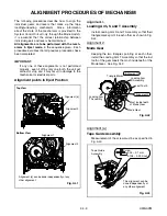
Alignment 3
Cam Gear (A), Rack Assembly
Install the Rack Assembly so that the first tooth on
the gear of the Rack Assembly meets the first
groove on the Cam Gear (A) as shown in Fig. AL4.
Cam Gear (A)
First tooth
First groove
on the Cam Gear (A)
Alignment 3
Top View
Gear on Rack Assembly
Fig. AL4
Summary of Contents for 25A-664
Page 22: ...1 8 3 1 8 4 1 8 5 HC4S4SCM1 Main 1 5 Schematic Diagram ...
Page 23: ...1 8 6 1 8 7 1 8 8 HC4S4SCM2 Main 2 5 Schematic Diagram ...
Page 24: ...1 8 9 1 8 10 1 8 11 HC4S4SCM3 Main 3 5 Schematic Diagram ...
Page 26: ...Main 5 5 Schematic Diagram 1 8 15 1 8 16 HC4S4SCM5 ...
Page 27: ...VPS Schematic Diagram 1 8 17 1 8 18 HC4S4SCV ...
Page 28: ...1 8 19 1 8 20 HC4S4SCF Function Schematic Diagram ...
Page 29: ...AFV Schematic Diagram 1 8 21 1 8 22 HC4S4SCAFV ...
Page 30: ...Jack Schematic Diagram 1 8 23 1 8 24 HC4S4SCJ ...
Page 31: ...1 8 25 1 8 26 Function CBA Top View Function CBA Bottom View BHC400F01018 B ...
Page 33: ...1 8 29 1 8 30 Jack CBA Top View Jack CBA Bottom View BHC400F01018 E ...
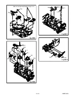
Page 54: ...2 4 6 U25PALDA S 12 19 Cap Belt Fig DM11 Fig DM12 20 C 1 21 ...
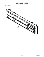
Page 60: ...3 1 1 HC4C0FEX A1X EXPLODED VIEWS Front Panel ...
Page 81: ...25A 664 HC4S4ED ...

