1-5-1
HC2C0DC
CABINET DISASSEMBLY INSTRUCTIONS
1. Disassembly Flowchart
This flowchart indicates the disassembly steps to gain
access to item(s) to be serviced. When reassembling,
follow the steps in reverse order. Bend, route, and
dress the cables as they were originally.
2. Disassembly Method
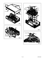
(1): Identification (location) No. of parts in the figures
(2): Name of the part
(3): Figure Number for reference
(4): Identification of parts to be removed, unhooked,
unlocked, released, unplugged, unclamped, or
desoldered.
P=Spring, L=Locking Tab, S=Screw,
CN=Connector
*=Unhook, Unlock, Release, Unplug, or Desolder
e.g. 2(S-2) = two Screws (S-2),
2(L-2) = two Locking Tabs (L-2)
(5): Refer to “Reference Notes.”
Reference Notes
CAUTION: Locking Tabs (L-1) and (L-2) are fragile.
Be careful not to break them.
1. Release Locking Tab (L-3) and remove Screw
(S-2), five Screws (S-3), three Screws (S-4) and
Screw (S-5). Then, slowly lift the VCR Chassis Unit
(Deck Assembly, Function CBA, Jack CBA and
Main CBA) up.
2. When reassembling, solder wire jumpers as shown
in Fig. 5.
3. Before installing the Deck Assembly, be sure to
place the pin of LD-SW on Main CBA as shown in
Fig. 6. Then, install the Deck Assembly while align-
ing the hole of Cam Gear with the pin of LD-SW,
the shaft of Cam Gear with the hole of LD-SW as
shown in Fig. 6.
ID/
LOC.
No.
PART
REMOVAL
Fig.
No.
REMOVE/*UNHOOK/
UNLOCK/RELEASE/
UNPLUG/DESOLDER
Note
[1]
Top Case
1
7(S-1)
-
[2]
Front
Assembly
2
*3(L-1),*4(L-2)
-
[3]
VCR
Chassis
Unit
3
*(L-3), 5(S-3), 3(S-4),
(S-5)
1
[4]
Jack CBA
4
Desolder, (S-6)
-
[5]
Function
CBA
5
Desolder
-
[6]
Deck
Assembly
5,6
2(S-7), Desolder
2,3
[7]
Main CBA
5
----------
-
↓
(1)
↓
(2)
↓
(3)
↓
(4)
↓
(5)
[5] Function CBA
[4] Jack CBA
[1] Top Case
[2] Front Assembly
[3] VCR Chassis Unit
[6] Deck Assembly
[7] Main CBA
Summary of Contents for 25A-664
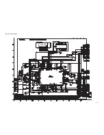
Page 22: ...1 8 3 1 8 4 1 8 5 HC4S4SCM1 Main 1 5 Schematic Diagram ...
Page 23: ...1 8 6 1 8 7 1 8 8 HC4S4SCM2 Main 2 5 Schematic Diagram ...
Page 24: ...1 8 9 1 8 10 1 8 11 HC4S4SCM3 Main 3 5 Schematic Diagram ...
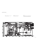
Page 26: ...Main 5 5 Schematic Diagram 1 8 15 1 8 16 HC4S4SCM5 ...
Page 27: ...VPS Schematic Diagram 1 8 17 1 8 18 HC4S4SCV ...
Page 28: ...1 8 19 1 8 20 HC4S4SCF Function Schematic Diagram ...
Page 29: ...AFV Schematic Diagram 1 8 21 1 8 22 HC4S4SCAFV ...
Page 30: ...Jack Schematic Diagram 1 8 23 1 8 24 HC4S4SCJ ...
Page 31: ...1 8 25 1 8 26 Function CBA Top View Function CBA Bottom View BHC400F01018 B ...
Page 33: ...1 8 29 1 8 30 Jack CBA Top View Jack CBA Bottom View BHC400F01018 E ...
Page 54: ...2 4 6 U25PALDA S 12 19 Cap Belt Fig DM11 Fig DM12 20 C 1 21 ...
Page 60: ...3 1 1 HC4C0FEX A1X EXPLODED VIEWS Front Panel ...
Page 81: ...25A 664 HC4S4ED ...


