background image

86

Service Supplement


PRIMERGY CX122 S1

Replacing the power supply unit

Ê

Reinstall all components into the replacement chassis (S26361-K1348-
V900) as shown in the related sections:

Processors: 

section "Installing a processor" on page 63

Heat sinks: 

section "Installing a heat sink" on page 66

Memory modules: 

section "Installing a memory module" on page 74

Expansion cards: 

section "Replacing expansion cards" on page 48

PCI riser card: 

section "Replacing the PCI riser card" on page 53

System board: 

section "Replacing the system board" on page 77

Ê

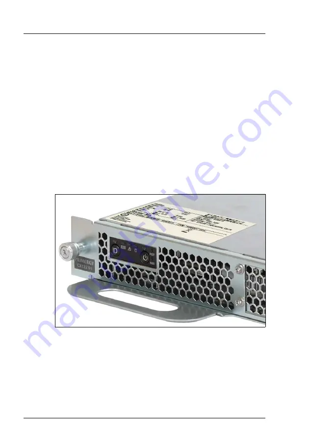
Mount the server cover of the original chassis (including the defective PSU) 
onto the replacement chassis as described in 

section "Closing the server" 

on page 33

.

I

Ensure that the type label on the server cover is in place:

Summary of Contents for PRIMERGY CX122 S1

Page 1: ...Service Supplement English PRIMERGY CX122 S1 Server Service Supplement November 2010 ...

Page 2: ... Copyright and Trademarks Copyright 2010 Fujitsu Technology Solutions GmbH All rights reserved Delivery subject to availability right of technical modifications reserved All hardware and software names used are trademarks of their respective manufacturers The contents of this manual may be revised without prior notice Fujitsu assumes no liability for damages to third party copyrights or other righ...

Page 3: ...oard assemblies and in the mouse and keyboard are limited life components Use of these components beyond their operating life may result in electrolyte leakage or depletion potentially causing emission of foul odor or smoke As a guideline in a normal office environment 25 C operating life is not expected to be reached within the maintenance support period 5 years However operating life may be reac...

Page 4: ...nal Computer issued by JEITA the Japan Electronics and Information Technology Industries Association Technology controlled by the Foreign Exchange and Foreign Trade Control Law of Japan Documents produced by FUJITSU may contain technology controlled by the Foreign Exchange and Foreign Trade Control Law of Japan Documents which contain such technology should not be exported from Japan or transferre...

Page 5: ...a PRIMERGY CX122 S1 server in the system unit 21 4 1 2 1 Rack installation 21 4 1 2 2 Network cabling 24 4 1 3 Handling server dummy covers 28 4 1 3 1 Installing a server dummy cover 28 4 1 3 2 Removing a server dummy cover 30 4 1 4 Opening and closing the server 31 4 1 4 1 Opening the server 31 4 1 4 2 Closing the server 33 4 2 Replacing the front panel module 34 4 3 Replacing the hard disk drive...

Page 6: ...lling a heat sink 66 4 5 6 Installing air ducts 68 4 6 Installing replacing memory modules 70 4 6 1 Removing a memory module 73 4 6 2 Installing a memory module 74 4 6 3 Removing installing a memory dummy module 76 4 7 Replacing the system board 77 4 8 Replacing the power supply unit 84 5 Appendix 87 5 1 Used screws 87 5 2 Board layout 88 5 2 1 Front panel board 88 5 2 2 PCI riser card D2894 A10 8...

Page 7: ... Concept and target groups This Service Supplement completes the information given in the Operating Manual and the Technical Manual of the system board The activities described in this manual may only be performed by service personnel Service DVD Service partners of Fujitsu Technology Solutions GmbH can order a Service DVD PRIMERGY On the DVD the following manuals are available in pdf format The S...

Page 8: ...atures of the system board Board layout Jumper settings Replacing the battery Technical Manual Extensions and upgrades Extending replacing the main memory Installing expansion boards in the PCI slots Service Supplement Operating Manual Network Cabling Replacement routines Replacing the front panel module Replacing the power supply unit Replacing HDDs Replacing the riser cards expansion boards Repl...

Page 9: ...ands or menu items Quotation marks indicate names of chapters and terms that are being emphasized Ê describes activities that must be performed in the order shown V CAUTION pay particular attention to texts marked with this symbol Failure to observe this warning may endanger your life destroy the system or lead to the loss of data I indicates additional information notes and tips ...

Page 10: ......

Page 11: ...ely need the Operating Manual for the server and the Technical Manual for the system board Ê Shut down the server correctly switch it off remove it from the system unit and open the server as described in the section Opening the server on page 31 Ê Replace the defective component as described in the associated chapter Ê Close the server as described in section Closing the server on page 33 Ê Reins...

Page 12: ......

Page 13: ...the device Wait until the device has acclimatized to room temperature and is absolutely dry before starting it up Material damage may be caused to the device if this requirement is not observed Transport the device only in the original packaging or in packaging that protects it from knocks and jolts Installation and operation V CAUTION This unit should not be operated in ambient temperatures above...

Page 14: ...ply with EN 50173 and EN 50174 1 2 standards or ISO IEC 11801 standard respectively The minimum requirement is a Category 5 shielded cable for 10 100 Ethernet or a Category 5e cable for Gigabit Ethernet Route the cables in such a way that they do not create a potential hazard make sure no one can trip over them and that they cannot be damaged When connecting the server refer to the relevant instru...

Page 15: ...turn off the server all peripheral devices and any other connected devices Do not damage or modify internal cables or devices Doing so may cause a device failure fire or electric shock Devices inside the server remain hot after shutdown Wait for a while after shutdown before installing or removing internal options The circuit boards and soldered parts of internal options are exposed and can be dam...

Page 16: ... provided with the chemical symbol of the heavy metal decisive for the classification as a pollutant Cd Cadmium Hg Mercury Pb Lead Working with CDs DVDs BDs and optical drives When working with external optical drives these instructions must be followed V CAUTION Only use CDs DVDs BDs that are in perfect condition in order to prevent data loss equipment damage and injury Check each CD DVD BD for d...

Page 17: ...avoid contact with the disk surface Do not contaminate the CD DVD BD surface with fingerprints oil dust etc If dirty clean with a soft dry cloth wiping from the center to the edge Do not use benzene thinners water record sprays antistatic agents or silicone impregnated cloth Be careful not to damage the CD DVD BD surface Keep the CDs DVDs BDs away from heat sources Do not bend or place heavy objec...

Page 18: ...ng the following suggestions Only insert disks in the drive when needed and remove them after use Store the disks in suitable sleeves Protect the disks from exposure to heat and direct sunlight Laser information The optical drive complies with IEC 60825 1 laser class 1 V CAUTION The optical drive contains a light emitting diode LED which under certain circumstances produces a laser beam stronger t...

Page 19: ...ct before working with such components Any devices or tools that are used must be free of electrostatic charge Wear a suitable grounding cable that connects you to the external chassis of the system unit Always hold components with ESDs at the edges or at the points marked green touch points Do not touch any connectors or conduction paths on an ESD Place all the components on a pad which is free o...

Page 20: ......

Page 21: ...22 S1 server is maintained by Fujitsu service technicians The warranty is void if the server is damaged during installation or replacement of system expansions Figure 2 Front panel On Off button and power on indicator Ê Shut down the server properly The power on indicator 2 turns off I If the server does not shut down completely press the On Off button 1 for at least four seconds and or send a cor...

Page 22: ...ver from the system unit A Ê Disconnect all cables from the server I Cable guides ensure that the network cables remain located at their designated height units when unplugged Figure 4 Removing a server from the system unit B Ê Loosen the two knurled screws on the front cover 1 ...

Page 23: ...rver from the system unit that is not replaced immediately always install a dummy cover in the empty installation bay For further information please refer to section Installing a server dummy cover on page 28 4 1 2 Installing a PRIMERGY CX122 S1 server in the system unit 4 1 2 1 Rack installation No additional mechanical parts such as support brackets or screws are required for the installation of...

Page 24: ... 6 Mounting a server in the rack B Ê Insert the server into the rack at the desired installation position Ê Slide the server in the direction of the arrow until it stops 1 I By doing so the PRIMERGY CX122 S1 power supply will be connected automatically with the power distribution unit in the CX1000 S1 system unit Ê Secure the server with two knurled screws 2 ...

Page 25: ...PRIMERGY CX122 S1 Service Supplement 23 Preparations Figure 7 Mounting a server in the rack C Ê Reconnect all cables as described in section chapter Replacement routines on page 24 ...

Page 26: ...switches There are five different configurations of the PRIMERGY CX1000 S1 system unit The color coded LAN cables are assigned to the PRIMERGY CX122 S1 network ports as follows LAN switches Cable sets S26361 F3608 E1 1 onboard LAN 1 2 onboard LAN 2 green blue S26361 F3608 E2 1 onboard LAN 1 2 onboard LAN 2 5 Service LAN green blue black S26361 F3608 E3 1 onboard LAN 1 2 onboard LAN 2 3 LAN Card 1 ...

Page 27: ...PRIMERGY CX122 S1 Service Supplement 25 Preparations Figure 8 LAN cabling color coding servers ...

Page 28: ... Server 3 Port 7 SW1P7 Port 1 SV3P1 Switch 2 to Server 3 Port 7 SW2P7 Port 2 SV3P2 Switch 1 to Server 4 Port 8 SW1P8 Port 1 SV4P1 Switch 2 to Server 4 Port 8 SW2P8 Port 2 SV4P2 and so on Connection Switch Server Port Label Port Label Switch 3 to Server 1 Port 5 SW3P5 Port 3 SV1P3 Switch 4 to Server 1 Port 5 SW4P5 Port 4 SV1P4 Switch 3 to Server 2 Port 6 SW3P6 Port 3 SV2P3 Switch 4 to Server 2 Port...

Page 29: ...6 Switch 5 to Server 2 Port 6 SW5P6 Port 5 SV2P5 Switch 6 to Server 2 Port 6 SW6P6 Port 6 SV2P6 Switch 5 to Server 3 Port 7 SW5P7 Port 5 SV3P5 Switch 6 to Server 3 Port 7 SW6P7 Port 6 SV3P6 Switch 5 to Server 4 Port 8 SW5P8 Port 5 SV4P5 Switch 6 to Server 4 Port 8 SW6P8 Port 6 SV4P6 and so on Connection Switch Server Port Label Port Label Switch 5 to Server 1 Port 5 SW5P5 Port SL SV1SL Switch 5 to...

Page 30: ...ng a server dummy cover V CAUTION When removing a PRIMERGY CX122 S1 server from the system unit that is not replaced immediately always install a dummy cover in the empty installation bay Figure 9 Installing a server dummy cover A Ê Remove the two exposed cage nuts from the left and right support uprights ...

Page 31: ...ement 29 Preparations Figure 10 Installing a server dummy cover B Ê Hinge the catch on the dummy cover to the middle notch of the left support upright 1 Ê Rotate the dummy cover in the direction of the arrow until it locks in place 2 ...

Page 32: ...ft on the locking lever to disengage the locking mechanism Figure 12 Removing a server dummy cover B Ê Rotate the dummy cover in the direction of the arrow 1 and remove it from the installation bay 2 Ê When installing a server after removing the dummy cover fit two cage nuts in the middle notches on the left and right support uprights see figure 5 on page 21 ...

Page 33: ...ving a PRIMERGY CX122 S1 server from the system unit on page 19 V CAUTION When removing a PRIMERGY CX122 S1 server from the system unit that is not replaced immediately always install a dummy cover in the empty installation bay For further information please refer to section Installing a server dummy cover on page 28 Figure 13 Opening the server A Ê Loosen two screws on the server rear ...

Page 34: ...32 Service Supplement PRIMERGY CX122 S1 Preparations Figure 14 Opening the server B Ê Lift up 1 and remove 2 the server cover as shown ...

Page 35: ... 4 1 4 2 Closing the server Figure 15 Closing the server A Ê Fit the four tabs on the server cover into the slots in the front upper edge of the chassis 1 Ê Carefully rotate the server cover in the direction of the arrow 2 Figure 16 Closing the server B ...

Page 36: ...n the system unit as described in section Installing a PRIMERGY CX122 S1 server in the system unit on page 21 4 2 Replacing the front panel module Ê Open the server as described in section Opening the server on page 31 The pre assembled front panel module consists of the operating panel board and the operating panel holder including controls and LED indicators Part number A3C40114973 ...

Page 37: ...ard disk drive cage Ê Loosen one screw on the hard disk drive cage as shown 1 I Do not remove the screws completely Ê Slide the hard disk drive cage about five centimeters in the direction of the arrow 2 until the locking mechanism disengages Ê Lift the hard disk drive cage out of its mounting bay ...

Page 38: ...anel module Figure 18 Removing the front panel module Ê Disengage the two locking lugs on the front panel module from the hard disk drive cage as shown 1 Ê Remove the front panel module to the front 2 Ê Disconnect the front panel cable from the defective module 3 ...

Page 39: ...ng the front panel module Figure 19 Attaching the front panel module Ê Reconnect the front panel cable to the replacement front panel module 1 Ê Attach the replacement front panel module to the hard disk drive cage 2 until the locking lugs engage 3 ...

Page 40: ...acing the front panel module Figure 20 Inserting the hard disk drive cage A Ê Lower the hard disk drive cage into its mounting bay so that the clip on the server floor A is positioned within the recess on the bottom of the hard disk drive cage B ...

Page 41: ...e cage B Ê Slide the hard disk drive cage towards the server front 1 as shown until the hook on the HDD cage engages with the retaining screw Ê Fasten the retaining screw C26192 Y10 C67 to secure the hard disk drive cage Screw torque 0 6 Nm Ê Close the server as described in section Closing the server on page 33 ...

Page 42: ...p to two non user replaceable 2 5 inch SATA hard disk drives Ê Open the server as described in section Opening the server on page 31 HDD part numbers SATA 160 GB 5 4k rpm S26361 F3599 L160 SATA 320 GB 5 4k rpm S26361 F3599 L320 SATA 500 GB 5 4k rpm S26361 F3599 L500 BC SATA 160 GB 7 2k rpm S26361 F3625 L160 BC SATA 500 GB 7 2k rpm S26361 F3625 L500 ...

Page 43: ...rd disk drive cage Ê Loosen one screw on the hard disk drive cage as shown 1 I Do not remove the screws completely Ê Slide the hard disk drive cage about five centimeters in the direction of the arrow 2 until the locking mechanism disengages Ê Lift the hard disk drive cage out of its mounting bay ...

Page 44: ...isk drives Figure 23 Disconnecting cables from the hard disk drive cage Ê Disconnect the front panel cable from the front panel module 1 Ê Disconnect the SATA and power cables from the hard disk drive s 2 Ê Lift the the hard disk drive cage out of the chassis 3 ...

Page 45: ... the hard disk drives Figure 24 Removing the hard disk drives from the HDD cage Ê Remove four screws per HDD from the hard disk drive cage Lower drive bay Primary HDD Upper drive bay Secondary HDD Ê Remove the defective hard disk drive s from the cage ...

Page 46: ...ing the hard disk drives Figure 25 Inserting the primary hard disk drive into the HDD cage Ê Insert the primary replacement hard disk drive into the lower drive bay of the HDD cage Figure 26 Inserting the secondary hard disk drive into the HDD cage ...

Page 47: ...placement or additional hard disk drive into the upper drive bay of the HDD cage Figure 27 Securing the hard disk drives in the HDD cage Ê Secure each hard disk drive in the HDD cage with four screws C26192 Y10 C56 Screw torque 0 4 Nm Ê Reconnect the SATA and power cables to the hard disk drive s ...

Page 48: ...lacing the hard disk drives Figure 28 Inserting the hard disk drive cage A Ê Lower the hard disk drive cage into its mounting bay so that the clip on the server floor A is positioned within the recess on the bottom of the hard disk drive cage B ...

Page 49: ... cage B Ê Slide the hard disk drive cage towards the server front 1 as shown until the hook on the HDD cage engages with the retaining screw Ê Fasten the retaining screw C26192 Y10 C67 to secure the hard disk drive cage Screw torque 0 6 Nm Ê Close the server as described in section Closing the server on page 33 ...

Page 50: ...iser card D2894 S26361 D2894 A10 1 R791 4 4 1 Replacing expansion cards Ê Open the server as described in section Opening the server on page 31 Part numbers Quad Port Gigabit Ethernet Controller D2745 CU S26361 D2745 A11 1 R791 Dual Port Gigabit Ethernet Controller D2735 CU S26361 D2735 A11 1 R791 Dual Port 10 Gbit Ethernet Controller Intel X520 DA2 INE E10G42BTDAG1P5 ...

Page 51: ...PRIMERGY CX122 S1 Service Supplement 49 Expansion cards Figure 30 Removing the PCI slot cover retaining bracket A Ê Press up on the PCI slot cover retaining bracket 1 and remove it 2 ...

Page 52: ...cards Figure 31 Removing the expansion card Ê Carefully ease the expansion card out of its connector 1 and remove the defective card 2 I If the expansion card is permanently removed from the server install a slot bracket in the empty card slot opening ...

Page 53: ...Installing an expansion card Ê Insert the replacement expansion card into the PCI connector on the riser card and press in firmly see blue arrows while holding up the riser card from the opposite side see orange arrow Ê Ensure that the card is fully seated in the slot ...

Page 54: ...lot cover retaining bracket into the card slot opening Ensure that the lower end of the retaining bracket engages with the clip on the server front 1 see circle Ê Press down on the PCI slot cover retaining bracket until it is flush with the chassis surface 2 Ê Close the server as described in section Closing the server on page 33 ...

Page 55: ...rver as described in section Opening the server on page 31 Ê Remove the expansion card as described in section Replacing expansion cards on page 48 Figure 34 Removing the PCI riser card Ê Pull the defective PCI riser card out the of riser card slot in a vertical motion Part number S26361 D2894 A10 1 R791 ...

Page 56: ...PCI riser card into the onboard riser card slot and press down firmly Ensure that the card is fully seated in the slot Ê Reinsert the expansion card into the PCI connector on the riser card as described in section Replacing expansion cards on page 48 Ê Close the server as described in section Closing the server on page 33 ...

Page 57: ...sor over a surface Supported processors Part numbers Intel Xeon E5506 V26808 B8313 V12 Intel Xeon L5620 V26808 B8456 V10 Intel Xeon L5630 V26808 B8454 V10 Intel Xeon L5640 V26808 B8455 V10 Intel Xeon X5670 V26808 B8458 V12 LGA1366 FSB Clock Speed Cores Threads L3 Cache Codename Xeon E5506 800 MHz 2 13 GHz 4C 8T 4 MB Nehalem EP Xeon L5620 800 MHz 2 40 GHz 4C 8T 12 MB Westmere Xeon L5630 800 MHz 2 1...

Page 58: ...Removing air ducts Ê Open the server as described in section Opening the server on page 31 Figure 36 Removing the CPU 1 air duct Ê Unhinge the hook on the CPU 1 air duct from the chipset heat sink bracket as shown 1 Ê Carefully lift the CPU 1 air duct out of the chassis 2 ...

Page 59: ...PRIMERGY CX122 S1 Service Supplement 57 Replacing the processor Figure 37 Removing the CPU 2 air duct Ê Carefully lift the CPU 2 air duct out of the chassis ...

Page 60: ... S1 Replacing the processor 4 5 2 Removing a heat sink Ê Open the server as described in section Opening the server on page 31 Figure 38 Removing the heat sink A Ê Loosen the four captive screws on the heat sink in a crossover pattern 1 4 ...

Page 61: ...at sink out of the chassis I Due to the adhesive quality of the thermal paste located between the heat sink and processor it may be necessary to turn the heat sink back and forth to detach the it from the processor Ê Thoroughly clean residual thermal paste from the surface of the heat sink using a lint free cloth ...

Page 62: ...vice Supplement PRIMERGY CX122 S1 Replacing the processor 4 5 3 Removing a processor Figure 40 Removing the processor A Ê Push down and out on the socket release lever 1 Ê Fold back the socket release lever 2 ...

Page 63: ...PRIMERGY CX122 S1 Service Supplement 61 Replacing the processor Figure 41 Removing the processor B Ê Open the processor cover ...

Page 64: ...ERGY CX122 S1 Replacing the processor Figure 42 Removing the processor C Ê Carefully remove the defective processor from its socket in a vertical motion V CAUTION Be careful not to touch or bend the pins on the processor socket ...

Page 65: ...er and align the pin 1 corners 1 of the processor and socket Ê Carefully seat the CPU in the socket 2 V CAUTION Ensure that the processor is level in the socket Be careful not to touch or bend the pins on the processor socket Never touch the underside of the processor Even minor soiling such as grease from the skin can impair the processor s operation or destroy the processor ...

Page 66: ...64 Service Supplement PRIMERGY CX122 S1 Replacing the processor Figure 44 Installing the processor B Ê Close the processor cover ...

Page 67: ...vot the socket release lever back toward the socket 1 and snap it into place to secure the processor 2 Ê Reapply a small amount of thermal paste to the surface of the processor Thermal paste part number FSP P304000003 Ê Ensure a thin and even distribution of thermal paste before reinstalling the heat sink ...

Page 68: ...pplement PRIMERGY CX122 S1 Replacing the processor 4 5 5 Installing a heat sink Figure 46 Installing the heat sink A Ê Carefully seat the heat sink on the four threaded holes as shown Part number V26898 B961 V1 Z175 ...

Page 69: ...that the screws on the heat sink are properly seated on the threaded holes Ensure that the heat sink cooling fins match the direction of the airflow Figure 47 Installing the heat sink B Ê Fasten the four captive screws on the heat sink in a crossover pattern screw torque 0 6 Nm 1 4 ...

Page 70: ...ing the processor 4 5 6 Installing air ducts Figure 48 Installing the CPU 1 air duct Ê Carefully fit the CPU 1 air duct onto the CPU 1 heat sink and memory modules 1 Ê Hinge the hook on the CPU 1 air duct to the chipset heat sink bracket as shown 2 ...

Page 71: ... Service Supplement 69 Replacing the processor Figure 49 Installing the CPU 2 air duct Ê Carefully fit the CPU 2 air duct onto the CPU 2 heat sink Ê Close the server as described in section Closing the server on page 33 ...

Page 72: ... channels Three channels per processor are available Supported memory modules DDR3 800 PC3 6400 DDR3 1066 PC3 8500 or DDR3 1333 PC3 10600 unbuffered and registered DIMMs UDIMMs RDIMMs with ECC Supported capacities 2 GB 4 GB or 8 GB Maximum amount of RAM 144 GB Part numbers 2 GB DDR3 1333 UDIMM S26361 F3597 L513 4 GB DDR3 1333 RDIMM S26361 F3598 L514 8 GB DDR3 1333 RDIMM S26361 F3598 L515 ...

Page 73: ...PRIMERGY CX122 S1 Service Supplement 71 Installing replacing memory modules Population sequence Figure 50 Memory slots ...

Page 74: ...x x x 4 x x x x 5 x x x x x 6 x x x x x x 7 x x x x x x x 8 x x x x x x x x 9 x x x x x x x x x Table 4 Memory installation sequence CPU 1 Modules per CPU Processor Socket 2 Channel F Channel E Channel D 1F 2F 3F 1E 2E 3E 1D 2D 3D 1 x 2 x x 3 x x x 4 x x x x 5 x x x x x 6 x x x x x x 7 x x x x x x x 8 x x x x x x x x 9 x x x x x x x x x Table 5 Memory installation sequence CPU 2 ...

Page 75: ...n Removing air ducts on page 56 Figure 51 Removing a memory module Ê Eject the defective memory module by pressing out the securing clips at each end of the memory module connector V CAUTION In order to satisfy cooling requirements please note When removing a memory module that is not replaced immediately always install a memory dummy module in the empty memory slot as described in section Removin...

Page 76: ...ules 4 6 2 Installing a memory module Figure 52 Installing a memory module A Ê Press out the securing clip at each end of the memory module connector Figure 53 Installing a memory module B Ê Align the notch on the bottom of the module with the crossbar in the connector X X ...

Page 77: ...memory module C Ê Press down on the memory module 1 until the securing clips snap into the cutouts at each end of the module 2 Ê If applicable reinstall the CPU 1 air duct as described in section Installing air ducts on page 68 Ê Close the server as described in section Closing the server on page 33 ...

Page 78: ...tely always install a memory dummy module in the empty memory slot Removing a memory dummy module Figure 55 Removing a memory dummy module Ê Eject the memory dummy module by pressing out the securing clips at each end of the memory module connector Installing a memory dummy module Ê Lower the memory dummy module into the memory slot Ê Press down on the memory dummy module until the securing clips ...

Page 79: ...move the following components from the system board as shown in the related sections Heat sinks section Removing a heat sink on page 58 Processors section Removing a processor on page 60 Memory modules section Removing a memory module on page 73 Expansion cards section Replacing expansion cards on page 48 PCI riser card section Replacing the PCI riser card on page 53 System board D2899 Part number...

Page 80: ...ing the system board Figure 56 Removing the system board A Ê Remove eight screws from the system board see circles Ê Slightly lift the system board by the memory module ejectors and the PCI riser slot in order to detach it from the centering holes ...

Page 81: ...he system board B Ê Carefully shift the system board towards the server rear until the plug shells disengage from the cut outs in the connector panel 1 Ê Hold the defective system board by the memory module ejectors and the PCI riser slot and at a slight angle lift it out of the housing 2 ...

Page 82: ... or handle the system board by any of its heat sinks Ensure not to damage the EMI springs to comply with applicable EMC regulations and satisfy cooling requirements and fire protection measures Ê At a slight angle insert the system board into the housing in the direction of the arrow 1 Ê Carefully shift the system board towards the server front until the plug shells engage with the cut outs in the...

Page 83: ...e system board Figure 59 Installing the system board B Ê Carefully fit the system board into the housing Ê Secure the system board with eight screws M3 x 6 mm C26192 Y10 C68 see circles I Screw torque 0 6 Nm Tighten the screws in a cross diagonal pattern ...

Page 84: ...tor PWR1 2 PSU connector P2 to system board connector PWR2 3 PSU connector P3 to system board connector PWR_AUX 4 Sideband cable T26139 Y4016 V1 from PSU connector CN2 to system board connector PWR_SIDEBAND 5 HDD power cable T26139 Y3930 V351 from PSU connector CN4 to system board connector PWR_HDD to HDD 1 HDD 2 6 Front panel board cable T26139 Y4010 V1 to system board connector FRONTPANEL ...

Page 85: ...s as shown in the related sections Processors section Installing a processor on page 63 Heat sinks section Installing a heat sink on page 66 Memory modules section Installing a memory module on page 74 Expansion cards section Replacing expansion cards on page 48 PCI riser card section Replacing the PCI riser card on page 53 Ê Close the server as described in section Closing the server on page 33 I...

Page 86: ...oving a heat sink on page 58 Processors section Removing a processor on page 60 Memory modules section Removing a memory module on page 73 Expansion cards section Replacing expansion cards on page 48 PCI riser card section Replacing the PCI riser card on page 53 System board section Replacing the system board on page 77 A pre assembled replacement chassis PSU kit is available under the following p...

Page 87: ... Remove the server cover from the replacement chassis as described in section Opening the server on page 31 Figure 63 Connecting cables to the PSU Ê If applicable connect power cables to the power supply unit 1 HDD power cable T26139 Y3930 V351 to PSU connector CN4 2 Sideband cable T26139 Y4016 V1 to PSU connector CN2 ...

Page 88: ...on page 66 Memory modules section Installing a memory module on page 74 Expansion cards section Replacing expansion cards on page 48 PCI riser card section Replacing the PCI riser card on page 53 System board section Replacing the system board on page 77 Ê Mount the server cover of the original chassis including the defective PSU onto the replacement chassis as described in section Closing the ser...

Page 89: ...vice Supplement 87 5 Appendix 5 1 Used screws Use Part number Type Figure Server cover HDD cage C26192 Y10 C67 M3 x 4 5 mm System board C26192 Y10 C68 M3 x 6 mm HDD cage C26192 Y10 C56 M3 x 4 mm Table 6 List of used screws ...

Page 90: ...yout 5 2 Board layout 5 2 1 Front panel board The pre assembled front panel module consists of the operating panel board and the operating panel holder including controls and LED indicators Part number A3C40114973 1 Front panel cable T26139 Y4010 V1 ...

Page 91: ...PRIMERGY CX122 S1 Service Supplement 89 Board layout 5 2 2 PCI riser card D2894 A10 Part number S26361 D2894 A10 1 R791 1 PCI Express x16 slot Gen2 for optional network controller ...

Page 92: ......

Page 93: ...8 46 removal 34 H hard disk drive cage installation 39 47 removal 35 41 hard disk drives 40 installation 44 removal 43 heat sink installation 66 removal 58 I installation in the system unit 21 L LAN cabling 24 laser information 16 light emitting diode LED 16 lithium battery 14 M meaning of the symbols 7 memory dummy module 76 memory modules 70 installation 74 population sequence 71 removal 73 N ne...

Page 94: ...Y CX122 S1 Index processor 55 installation 63 removal 60 PSU replacement 84 R removal from the system unit 19 riser card 48 53 S screws 87 System board 77 system board 77 installation 80 removal 77 T target group 5 U used screws 87 ...

Reviews: