


C141-E110-02EN
5 - 10
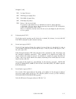
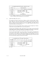
(6)
Cylinder Low register (X'1F4')
The contents of this register indicates low-order 8 bits of the starting cylinder address for any
disk-access.
At the end of a command, the contents of this register are updated to the current cylinder number.
Under the LBA mode, this register indicates LBA bits 15 to 8.
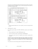
(7)
Cylinder High register (X'1F5')
The contents of this register indicates high-order 8 bits of the disk-access start cylinder address.
At the end of a command, the contents of this register are updated to the current cylinder number.
The high-order 8 bits of the cylinder address are set to the Cylinder High register.
Under the LBA mode, this register indicates LBA bits 23 to 16.
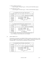
(8)
Device/Head register (X'1F6')
The contents of this register indicate the device and the head number.
When executing INITIALIZE DEVICE PARAMETERS command, the contents of this register
defines "the number of heads minus 1".
Bit 7
Bit 6
Bit 5
Bit 4
Bit 3
Bit 2
Bit 1
Bit 0
X
L
X
DEV
HS3
HS2
HS1
HS0
- Bit 7:
Unused
- Bit 6:
L. 0 for CHS mode and 1 for LBA mode.
- Bit 5:
Unused
- Bit 4:
DEV bit. 0 for the master device and 1 for the slave device.
- Bit 3:
HS3 CHS mode head address 3 (2
3
). LBA bit 27.
- Bit 2:
HS2 CHS mode head address 3 (2
2
). LBA bit 26.
- Bit 1:
HS1 CHS mode head address 3 (2
1
). LBA bit 25.
- Bit 0:
HS0 CHS mode head address 3 (2
0
). LBA bit 24.
Summary of Contents for MPG3xxxAT
Page 1: ...C141 E110 02EN MPG3xxxAT DISK DRIVES PRODUCT MANUAL ...
Page 3: ...This page is intentionally left blank ...
Page 15: ...This page is intentionally left blank ...
Page 31: ...C141 E110 02EN 3 2 Figure 3 1 Dimensions ...
Page 47: ...This page is intentionally left blank ...
Page 67: ...This page is intentionally left blank ...
Page 177: ...This page is intentionally left blank ...
Page 201: ......