


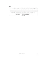

C141-E110-02EN
3 - 4
3.3
Mounting
(1)
Direction
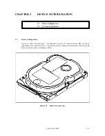
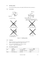
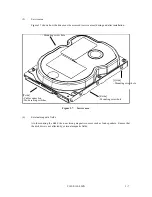
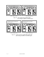
Figure 3.3 illustrates normal direction for the disk drive. The disk drives can be mounted in any
direction.
Horizontal mounting with the PCB facing down
Figure 3.3
Direction
(2)
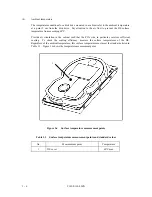
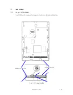
Frame
The disk enclosure (DE) body is connected to signal ground (SG) and the mounting frame is also
connected to signal ground. These are electrically shorted.
Note:
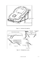
Use No.6-32UNC screw for the mounting screw and the screw length should satisfy the
specification in Figure 3.5.
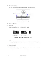
(3)
Limitation of side-mounting
When the disk drive is mounted using the screw holes on both side of the disk drive, use two
screw holes shown in Figure 3.4.
Do not use the center hole. For screw length, see Figure 3.5.
Summary of Contents for MPG3xxxAT
Page 1: ...C141 E110 02EN MPG3xxxAT DISK DRIVES PRODUCT MANUAL ...
Page 3: ...This page is intentionally left blank ...
Page 15: ...This page is intentionally left blank ...
Page 31: ...C141 E110 02EN 3 2 Figure 3 1 Dimensions ...
Page 47: ...This page is intentionally left blank ...
Page 67: ...This page is intentionally left blank ...
Page 177: ...This page is intentionally left blank ...
Page 201: ......