CHAPTER 3
Small Configuration
Installing Power, Ground, and Alarm Cables
FNC-7500-0061-200
Issue 1, May 2009
FLASHWAVE 7500 Release 6.1
Equipment Installation
3-94
Fujitsu and Fujitsu Customer Use Only
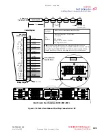
Figure 3-79: Optical/Tributary Shelf Alarm Cabling
(Small Configuration)
H.K.1
CN41
.2
CN40
Mo
CN4
FLASHWAVE 7500 Backplane
Cable Diagram
Wiring Diagram
Note:
Twisted-pair cables are paired per color code as shown in the
wiring diagram. This cable connects from the FLASHWAVE 7500
shelf connector CN42 to rack alarm harness HA660-1106-T003 at
CN-A, CN-B, CN-C, CN-D, CN-E, or CN-F.
HA660-1102-T015
SHLF ALM HARN
24 inches
FLASHWAVE 7500
Backplane
CN42
ALM
FG
1
3
2
4
BLU/WHT
WHT/GRN
5
GRN/WHT
6
WHT/SLT
SLT/WHT
7
RED/ORG
8
ORG/RED
9
RED/BRN
WHT/ORG
10
ORG/WHT
11
WHT/BRN
BRN/WHT
RED/BLU
BLU/RED
RED/GRN
GRN/RED
BRN/RED
25-Pin
D-Sub Connector
to Rack Alarm Harness
AUDCR
SG
AUDCRR
AUDMJ
AUDMJR
AUDMN
AUDMNR
VISCR
VISCRR
VISMJ
VISMN
CACO
CACOR
Connects FLASHWAVE 7500 shelves to the
multishelf rack alarm harness HA660-1106-T003
MISMJR
VISMNR
12
13
14
15
16
17
18
19
20
21
22
23
24
25
WHT/BLU
Cable Shield
1
3
2
4
5
6
7
8
9
10
11
12
13
14
15
16
17
18
19
20
21
22
23
24
25
25-Pin
D-Sub Connector
to FLASHWAVE 7500 Shelf
FNC Customer Support Part No.: HA660-1102-T015
FNC Mfg Part No.: Same
Part
Numbers
Application
ALM
CN42
m1
71
4nn
_1
Revision 1, June 2009
Summary of Contents for FLASHWAVE 7500
Page 8: ...Revision 1 June 2009 ...
Page 10: ...Revision 1 June 2009 ...
Page 16: ...Revision 1 June 2009 ...
Page 362: ...Revision 1 June 2009 ...
Page 386: ...Revision 1 June 2009 ...


