CHAPTER 2
Core Configuration
Installing Power, Ground, and Alarm Cables
2-49
FLASHWAVE 7500 Release 6.1
Equipment Installation
Fujitsu and Fujitsu Customer Use Only
FNC-7500-0061-200
Issue 1, May 2009
8
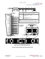
On the backplane of the shelf identified in
, remove the plastic cover on the
shelf power terminal strip located on the bottom right of the shelf backplane (see
).
9
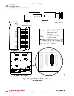
Connect both ends of cable GA of the power harness as follows:
a.
Identify lug GA in the power harness (see
) and connect it to shelf
terminal GA (see
b.
Connect the other end of the same cable to CBP terminal RTN A1 CB1 (see
).
10
Connect both ends of cable GB of the power harness as follows:
a.
Identify lug GB in the power harness (see
) and connect it to shelf
).
b.
Connect the other end of the same cable to CBP terminal RTN B1 CB1 (see
).
11
Connect both ends of cable MA of the power harness as follows:
a.
Identify lug MA in the power harness (see
) and connect it to shelf
terminal MAIN A (see
).
b.
Connect the other end of the same cable to CBP terminal BATT A1 CB1 (see
).
12
Connect both ends of cable MB of the power harness as follows:
a.
Identify lug MB in the power harness (see
) and connect it to shelf
terminal MAIN B (see
b.
Connect the other end of the same cable to CBP terminal BATT B1 CB1 (see
).
13
Connect both ends of cable FGND of the power harness as follows:
a.
Identify lug FGND in the power harness (see
) and connect it to
shelf terminal FG (see
).
b.
Connect the other end of the same cable to the equipment rack frame ground.
14
Replace the plastic cover over the shelf backplane terminal strip.
Revision 1, June 2009
Summary of Contents for FLASHWAVE 7500
Page 8: ...Revision 1 June 2009 ...
Page 10: ...Revision 1 June 2009 ...
Page 16: ...Revision 1 June 2009 ...
Page 362: ...Revision 1 June 2009 ...
Page 386: ...Revision 1 June 2009 ...


