background image


System expansion


Fujitsu Technology Solutions 

85 

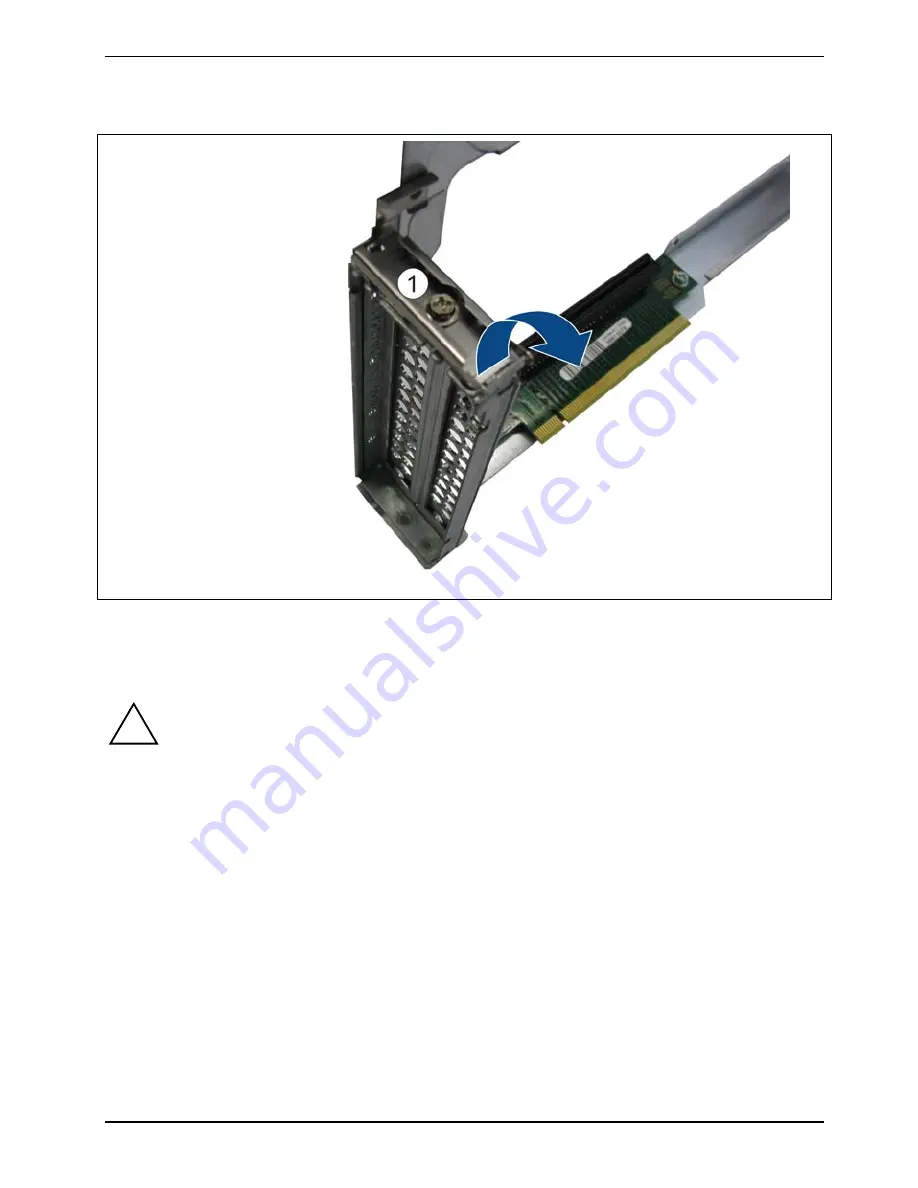
Removing slot covers 


Undo the screw (1). 


Fold the locking lever in the direction of the arrow. 


Pull the slot covers out. 


!


CAUTION!


Keep the slot cover of the slot. If you remove the expansion card again and do not insert a 
new one instead, you must replace the slot cover for cooling purposes, to comply with the 
conditions of the EMC (electromagnetic compatibility) regulations and to protect against 
fire.   


Summary of Contents for CELSIUS C620

Page 1: ...Operating Manual System CELSIUS C620 ...

Page 2: ...s fujitsu com You can find driver updates at http support de ts fujitsu com de support index html If you have any technical questions please refer to our Hotline our Service Desk see enclosed Service Desk list or visit our website at http ts fujitsu com support servicedesk html your Sales Partner your sales office We hope you enjoy working with your new Fujitsu system ...

Page 3: ......

Page 4: ...lity No warranty is offered or liability accepted in regard of the completeness correctness or current applicability of any data or illustrations Brand names may be protected trademarks of the respective manufacturer and or protected by copyright Use of these by third parties for their own purposes may constitute an infringement of the holders rights Further information can be found at http ts fuj...

Page 5: ... Rack mounting and dismounting 23 Connecting external devices 31 Connecting the device to the mains voltage 34 Switching the device on 35 Shutting down the device 36 Performing system configuration 37 Operation 39 Settings in BIOS Setup 43 Property and data protection 44 Troubleshooting and tips 46 System expansion 51 Technical data 104 Index 105 ...

Page 6: ... through the use of the information contained in this manual No part of this manual may be reproduced without the express written permission of Fujitsu Technology Solutions Copyright Fujitsu Technology Solutions GmbH 2012 All rights reserved including rights of translation reproduction by printing copying or similar methods either in part or in whole Offenders will be liable to prosecution and pay...

Page 7: ...22 Unpacking and checking the delivery 22 Rack mounting and dismounting 23 Specifications for the rack 23 Fujitsu rack systems 24 Installing the device in the rack 27 Insert the device in the telescopic rails 27 Slide the device into the rack 28 Connect the cables 28 Pulling out or removing the device from the rack 29 Pull the device out of the rack 29 Take the device out of the telescopic rails 3...

Page 8: ...53 Overview of the bays and drives in your device 54 Removing and installing an accessible 5 inch drive optical drive ODD 55 Removing the accessible 5 inch drive 55 Installing an accessible 5 inch drive 57 Changing the drive cage 58 Removing and installing non accessible drives hard disks HDD SSD 61 Removing and installing non accessible 2 inch drives hard disks HDD SSD 61 Removing and installing ...

Page 9: ...ing the heat sink 96 Installing the heat sink 97 Mainboard expansions 98 Upgrading main memory 98 Changing the processor 98 Changing the front panel module 99 Removing the front panel module 99 Installing a new front panel module 101 Replacing the lithium battery 103 Technical data 104 CELSIUS C620 104 Index 105 ...

Page 10: ...Contents 10 Fujitsu Technology Solutions ...

Page 11: ...otect access to your data e g by assigning password protection With certain operating systems DeskUpdate offers a simple and fast way to install the latest drivers and operating system upgrades using just a few mouse clicks DeskUpdate is included on the Drivers Utilities DVD Further information Further information on this device is also provided in the Quick Start Hardware booklet in the Safety Re...

Page 12: ...age to property Indicates instructions applied on the device failure to observe them endangers your health or leads to physical damage i indicates information and tips which are important for the proper use of the system Indicates a step that must be performed This font indicates screen displays This font indicates programme names commands or menu items Quotation marks indicate names of chapters d...

Page 13: ...s and operating elements on the device Please familiarise yourself with these components before you start to work with the device Front view 1 Optical drive 3 Buttons see Buttons on the device 4 Indicators see Indicators on the device 2 4 non accessible 2 inch drives depending on the drive cage installed or 5 USB ports 2 0 2 non accessible 3 inch drives depending on the drive cage installed ...

Page 14: ...Ports and controls 14 Fujitsu Technology Solutions Rear view 1 Power supply fan 5 Serial COM port 2 Power connection 6 LAN ports 3 ID indicator blue 7 USB ports 3 0 4 DVI I monitor port ...

Page 15: ...se the operator can be requested to take appropriate measures Safety notes Please follow the safety instructions given in the Safety Regulations manual and the safety instructions below While installing and operating the device please observe the instructions on environmental conditions in the Technical data section and the Preparation for initial startup section ON OFF switches do not disconnect ...

Page 16: ...side of the device Do not use any cleaning sprays especially not any flammable substances Damage to the device or a fire risk could occur The casing surfaces may be cleaned with a dry cloth If particularly dirty use a cloth that has been moistened in mild domestic detergent and then carefully wrung out You can use disinfectant wipes to clean the outside surfaces of the keyboard and the mouse Energ...

Page 17: ...nd Telecommunications Equipment and mutual recognition of conformity This equipment may be used in the following countries Belgium Denmark Germany Estonia Finland France Greece UK Ireland Iceland Italy Latvia Liechtenstein Lithuania Luxembourg Malta The Netherlands Norway Austria Poland Portugal Sweden Switzerland Slovakia Slovenia Spain Czech Republic Hungary Cyprus Bulgaria Rumania Contact the a...

Page 18: ...armful interference to radio or television reception which can be determined by turning the equipment off and on the user is encouraged to try to correct the interference by one or more of the following measures Reorient or relocate the receiving antenna Increase the separation between the equipment and receiver Connect the equipment into an outlet on a circuit different from that to which the rec...

Page 19: ...ply plugged in or pulled out Mixed configurations of SAS and SATA hard disk modules in one drive cage are not supported For up to four 2 5 inch SAS SATA hard disk drives Up to four 2 5 inch SAS SATA hard disk modules can be inserted into the drive cage Each HDD module can accept a SAS SATA hard disk drive in 2 5 inch format The connection of the modules to the SAS SATA backplane is wire free This ...

Page 20: ...s the iRMC S3 supports the following important functions Browser access via the iRMC S3 own web server Secure communication SSH SSL Power management for the managed device independent of its system status Command Line Interface CLI Easy interactive or script based configuration of the iRMC S3 Own iRMC S3 user management Global across processor iRMC S3 user administration using a LDAP directory ser...

Page 21: ... multitude of different finishes and varnishes used on furniture it is possible that the underside of the device will mark the surface it stands on Do not expose the device to extreme environmental conditions see Technical data Protect the device from dust humidity and heat Make sure that the device is adequately ventilated Do not stack several devices on top of each other Before putting it into o...

Page 22: ...ect the cables to the device In doing so please take note of section Connecting external devices Connect the device to the mains power see Connecting the device to the mains voltage Familiarise yourself with the operating controls and indicators on the front and rear of the device see section Ports and controls Switch on the device see section Switching the device on Configure the device and if ne...

Page 23: ...rack during assembly or service work If several units are pulled out of the rack simultaneously there is a danger of the rack tipping over The mains connection of the rack must be carried out by an authorised professional electrician If the device is incorporated into an installation supplied with power by an industrial supply network with a Type IEC 309 connection plug the fusing of the power sup...

Page 24: ...ections Installation of the cable management is described in detail in the technical manual for the particular rack 3rd party rack The following edge requirements must be met Installation dimensions see following illustration Key 1 front of rack 2 rear of rack A rack depth comparison PRIMECENTER Rack 940 1000 1100 mm B Rack width comparison PRIMECENTER Rack 700 mm C clear width of the 19 inch inst...

Page 25: ...Rack mounting and dismounting Fujitsu Technology Solutions 25 ...

Page 26: ...arious rack depths No support for the cable management supplied together with the installation kit Environmental conditions For ventilation of the installed device there must be an unobstructed air inlet at the front of the rack and an unobstructed air outlet at the rear of the rack As a basic principle the ventilation concept stipulates that the necessary cooling will be achieved by the horizonta...

Page 27: ...y lock in position 1 i In the process the telescopic rails must latch and it must no longer be possible to move them back Place the device at a slight angle onto the rear mounting points of the telescopic rails 2 Lower the device 3 Make certain that all six rack fastening bolts have been correctly secured in the fastening points of the telescopic rails and that the catches engage 4 ...

Page 28: ...sides 1 Slide the device as far into the rack 2 until the locking levers 3 engage CAUTION In doing so mind your fingers They could become trapped when the locking levers move into the open position Connect the cables Connect all the cables previously disconnected at the rear of the device Plug all the power cables into the power sockets ...

Page 29: ...l the device out of the rack without the anti tilt bracket being applied the rack will tip over Take care that no fingers or clothing items become trapped when sliding equipment in or out Otherwise you may be injured Please follow the safety instructions in the Important notes section Make sure that the device is shut down see section Shutting down the device Pull the device out of the rack Pull t...

Page 30: ...d dismounting 30 Fujitsu Technology Solutions Take the device out of the telescopic rails Release the latches on both telescopic rails 1 Lift the device out of the telescopic rails 2 and put it down on a level surface ...

Page 31: ...vice and peripheral equipment In every case always follow the safety instructions given in the section Important notes and in the Safety Regulations manual Plug the data communication cables into the data telephone network sockets Insert the power plugs into grounded power sockets Disconnecting cables Switch off all the equipment concerned For all the equipment concerned remove the power plugs fro...

Page 32: ...below or similar DVI I monitor port COM port USB 2 0 Universal Serial Bus black USB 3 0 Universal Serial Bus blue LAN LAN port i Special software e g drivers must be installed and configured for some of the devices that you connect see the operating system and device documentation Connecting a monitor Follow the instructions contained in the monitor manual to prepare the monitor for operation e g ...

Page 33: ...on for the USB devices Connect the data cable to the external device Connect the data cable to a USB port Read the documentation for the USB device to obtain full information about the installation of the device Device drivers i The devices you connect to the USB ports usually require no driver of their own as the required software is already included in the operating system However if the USB dev...

Page 34: ...device automatically adjusts itself to a mains voltage of 100 V 240 V You may only operate the device if the rated voltage range of the device matches the local mains voltage Connect the connector of the mains cable to the power supply of the device Plug the power plug into a non heating appliance socket on the power strip of the rack For more details please refer to the technical manual for the r...

Page 35: ... mains voltage the device needs a few seconds before you can switch it on Switch on the monitor refer to the operating manual for the monitor Press the ON OFF button on the front of your device for about half a second The power on indicator lights up see section Indicators on the device and the device starts ...

Page 36: ...hut down and switched off line Stop and close all applications Shut down the device i If there is an ACPI compatible operating system deployed on the system pressing the ON OFF button causes a controlled shutdown process or the device is put into standby mode depending on the setting Pay attention to the signaling of the power on indicator as described in the section Indicators on the device Switc...

Page 37: ...al drive with it i Additional information on configuration of the controller is given in the BIOS Setup manual i Descriptions of operating systems not covered in the controller manual are provided in the appropriate readme files on the driver CDs Configuring the SAS SATA controller The device has an optional SAS SATA RAID controller Depending on the version you can use up to 4 non accessible drive...

Page 38: ...be switched off unless the installation has been completed During the installation process DO NOT restart the device unless you are requested to do so Otherwise the installation will not be carried out correctly and the contents of the hard disk will have to be completely restored i If the device will be included in a network the user device and network protocol details are required during the sof...

Page 39: ...loss of data The ON OFF button does not disconnect the device from the mains voltage To completely disconnect from the mains voltage you must remove the power plug from the power socket ID Identification ID button When the ID button is pressed the ID indicators light up blue on the front and rear of the device Both ID indicators light synchronously RST Reset button Pressing the Reset button reboot...

Page 40: ...shutdown mode shutting down of the operating system or is switched off Hard disk activity green Lights green when an internal hard disk drive is being accessed Global error indicator orange Lights orange if a pre failure event was detected that requires a preventive service action Flashes orange if a fault was detected which requires a service action Unlit if there is no critical event present Aft...

Page 41: ...and the activity left of the LAN transfer No Description Description 1 LAN port 1 2 LAN port 2 The LED on the left lights green when a LAN connection is present is unlit if there is no LAN connection flashes green if a LAN transfer is occurring The LED on the right lights yellow LAN transfer 1 Gbit s lights green LAN transfer 100 Mbit s unlit LAN transfer 10 Mbit s ...

Page 42: ...ng the surface of a CD DVD Only hold CDs DVDs by their edges Always store CDs DVDs in their cases This will protect them from dust scratches and other damage Protect your CDs DVDs from dust mechanical vibration and direct sunlight Avoid storing a CD DVD in areas subject to high temperatures or humidity i You can use 12 cm diameter CDs DVDs in the drive Do not use any business card CDs or other sma...

Page 43: ...Setup i In BIOS Setup you can set the system functions and the hardware configuration of the device On delivery the default values are effective see the BIOS Setup manual or the manual for the mainboard You can customise these settings to your requirements in the BIOS Setup ...

Page 44: ...m and data internally from unauthorised access Mechanical casing lock optional With the casing lock you can mechanically lock the casing to prevent unauthorised persons from opening it The keys can be found on the rear panel of your device i In addition to the casing lock an open and a closed lock are also illustrated Locking the casing Turn the key towards the closed lock Unlocking the casing Tur...

Page 45: ...d access to BIOS Setup Prevent unauthorised system access Prevent unauthorised access to the settings of boards with their own BIOS Output virus warnings Protect BIOS from being overwritten Protect the device from being switched on by an external device You can also combine these functions You will find a detailed description of the Security menu and how to assign passwords in the manual for the m...

Page 46: ... cannot resolve yourself Note the ID number of your device The ID number can be found on the type rating plate on the top face of the casing For further clarification of the problem contact the Service Desk for your country see the Service Desk list or visit the Internet at http ts fujitsu com support servicedesk html Identifying defective devices When working in a data centre environment you shou...

Page 47: ...d into a grounded power outlet Switch the device on The device cannot be switched off with the ON OFF switch Cause Troubleshooting System crash Press the ON OFF switch for at least 5 seconds until the device switches off The operating system is not shut down properly in the process Error messages are therefore possible the next time the system is booted It may take a few seconds before the system ...

Page 48: ...e refer to the operating manual supplied with your monitor Power cable is not connected Switch off the monitor and the device Check that the monitor power cable is properly connected to the monitor and to a grounded power outlet or to the monitor socket of the device Check that the device power cable is properly plugged into the device and a grounded power outlet Switch on the monitor and the devi...

Page 49: ... and date are wrongly set Set the correct time and date under the operating system you are using or Set the correct time and or date in the BIOS Setup Error message on the monitor Error messages and their explanations are contained in the documentation for the programs used Installing new software When installing programs or drivers important files may be overwritten and modified You should make a...

Page 50: ...oo many applications running at once you may experience problems due to a lack of system resources Close unnecessary applications or Call up the applications in a different order Other manuals Further manuals can be found as PDF files on the Driver Utilities DVD or on the Internet at http ts fujitsu com support ...

Page 51: ...ce This section describes all the actions which you must perform if you wish to make hardware changes to your device e g installing boards or drives Read the supplied documentation before installing new drives and or boards Read the technical manual for the mainboard before making any expansion to the mainboard Information about boards Take care with the locking mechanisms catches and centring pin...

Page 52: ... by a short circuit caused by objects falling inside e g screws After finishing the maintenance work you must replace the casing cover to ensure cooling to comply with EMC Electromagnetic Compatibility regulations and to protect against fire Please follow the safety instructions in the Important notes section Make sure that the device is shut down see section Shutting down the device Where applica...

Page 53: ...unnecessary components or tools left inside the device Take care that no cables become trapped when the cover is put in place Place the casing cover on the device Slide the casing cover forwards until it reaches the stop The cover latches automatically Install the device in the rack again see section Installing the device in the rack ...

Page 54: ...le and non accessible drives one bay for an accessible 5 inch drive optical drive ODD depending on configuration a drive cage for four bays for non accessible 2 inch drives hard disks HDD SSD two bays for non accessible 3 inch drives hard disks HDD 1 Bay for accessible 5 inch drive 2 Drive cage example for four non accessible 2 inch drives ...

Page 55: ...e 5 inch drive Requirements The device is removed from the rack see section Pulling out or removing the device from the rack The casing is open see section Opening the device Disconnect the cables connected to the drive Unscrew the screw 1 on the drive cage Slide the drive in the direction of the arrow Lift the drive cage out of the device ...

Page 56: ... required settings on the remaining hard disk drives If required you must adjust the entry for the drive in the BIOS Setup accordingly If you do not install an accessible drive close off the open drive bay with the optional cover Close the device see section Closing the device Install the device in the rack again see section Installing the device in the rack ...

Page 57: ...ve cage from the device If necessary remove the cover of the drive bay Slide the drive into the drive cage and secure it with three screws Slide the drive cage into the drive bay in the direction of the arrow Tighten the screw 1 Connect the data and power supply cables Close the device see section Closing the device Install the device in the rack again see section Installing the device in the rack...

Page 58: ...cessible 2 inch drives Drive cage 2 for two non accessible 3 inch drives In the following example drive cage 1 is exchanged for drive cage 2 Requirements The device is removed from the rack see section Pulling out or removing the device from the rack The casing is open see section Opening the device If drives are installed remove them Disconnect the power and data cables from the mainboard and or ...

Page 59: ...tore the screws in the screw storage area 2 They are specially adapted for securing the drive cage Lift the drive cage slightly at the rear and slide it in the direction of the arrow 3 Remove the drive cage from the device Remove the cold plug cables from the drive cage ...

Page 60: ...y raised Slide the drive cage in the direction of the arrow and lower it at the same time Remove the screws from the screw storage area 2 and secure them 1 Connect the power and data cables at the mainboard and or the RAID controller Close the device see section Closing the device Install the device in the rack again see section Installing the device in the rack ...

Page 61: ...g system you may configure any write cache settings for the hard disk drive Should a power failure occur with an active write cache data could be lost If you dispose of a hard disk drive or solid state drive deliver it to a third party or wish to return it for your own security you should destroy any data saved on the drive Rough handling of hard disk drives can cause damage to the saved data Befo...

Page 62: ...Technology Solutions Mixed configurations of SAS and SATA HDD SSD modules are not supported If only one HDD SSD module is installed this must be placed in position 0 The remaining free locations must be occupied by an empty module ...

Page 63: ...o tongues on the empty module until the clip releases 1 Pull the empty module out of its location 2 CAUTION Keep the empty module If you have removed a drive and not replaced it with a new one then the empty module must be reinstalled for cooling purposes to comply with the conditions of the EMC electromagnetic compatibility regulations and to protect against fire Make certain that the empty modul...

Page 64: ...ch drive Requirements The empty module is removed see section Removing a 2 inch empty module To release the locking mechanism of the drive press together the two green tabs of the locking lever 1 Swing the grip of the drive fully in the direction of the arrow 2 The drive is released ...

Page 65: ...he drive into the free location 1 until it reaches a stop Press the grip fully in the direction of the arrow 2 until the locking mechanism engages i Where appropriate you must adjust the entry for the drive in BIOS Setup or in the configuration of the RAID controller ...

Page 66: ...configuration of the optional RAID controller can be found in the appropriate documentation on the Drivers Utilities DVD or on the Internet at http ts fujitsu com support CAUTION All the data on all the drives in the array will be lost Perform a backup before you delete a RAID array To release the locking mechanism of the drive press together the two green tabs of the locking lever Swing the grip ...

Page 67: ...on Fujitsu Technology Solutions 67 Installing a 2 inch empty module Requirement The drive is removed see section Removing a non accessible 2 inch drive Slide the empty module into the empty location until it engages ...

Page 68: ...isk drive with a maximum mounting height of 1 inch The connection of the HDD module to the SAS SATA backplane is wire free This allows the HDD modules to be simply plugged in or pulled out Mixed configurations of SAS and SATA HDD modules are not supported If only one HDD module is being installed it is placed in the location on the left hand side 0 an empty module must be installed in the location...

Page 69: ...o tongues on the empty module until the clip releases 1 Pull the empty module out of its location 2 CAUTION Keep the empty module If you have removed a drive and not replaced it with a new one then the empty module must be reinstalled for cooling purposes to comply with the conditions of the EMC electromagnetic compatibility regulations and to protect against fire Make certain that the empty modul...

Page 70: ...ch empty module To release the locking mechanism of the drive press the clip in the direction of the arrow 1 Swing the grip of the drive fully in the direction of the arrow 2 The drive is released Carefully slide the drive into the free location 1 until it reaches a stop Press the grip fully in the direction of the arrow 2 until the locking mechanism engages ...

Page 71: ... you must first of all delete the array i Further information on configuration of the optional RAID controller can be found in the appropriate documentation on the Drivers Utilities DVD or on the Internet at http ts fujitsu com support CAUTION All the data on all the drives in the array will be lost Perform a backup before you delete a RAID array To release the locking mechanism of the drive press...

Page 72: ...ling a 3 inch empty module Requirement The drive is removed see section Removing a non accessible 3 inch drive Slide the empty module into the empty location until it engages Install the device in the rack again see section Installing the device in the rack ...

Page 73: ...configuration the device has up to 6 system fans If no fan is installed at one of the positions in your device a placeholder made of foam must be installed at this position To ensure optimum cooling of the device the placeholder must not be removed under any circumstances Numbering of the fan modules ...

Page 74: ...ck see section Pulling out or removing the device from the rack The casing is open see section Opening the device CAUTION The fans are powerful high speed models Never remove the fans during operation because there is an increased risk of injury in doing so Pull the connector of the fan module out of the socket of the fan cable ...

Page 75: ...em expansion Fujitsu Technology Solutions 75 Lift the fan module by about 2 cm To do this press the four rubber pins upwards A Slide the fan cable through the opening of the fan cage Lift out the fan module ...

Page 76: ...nsion 76 Fujitsu Technology Solutions Installing a new fan module Guide the fan cable forwards through the opening in the fan cage and insert the fan module Press the four rubber pins A downwards until they engage ...

Page 77: ...Technology Solutions 77 Connect the connector of the fan module into the socket of the fan cable Close the device see section Closing the device Install the device in the rack again see section Installing the device in the rack ...

Page 78: ...otected and could be damaged by static electricity You must always discharge any static charge from your body e g by touching a grounded object before you change electrostatic sensitive devices ESDs Circuitry on boards or soldered components must not be touched Hold the circuitry by the metallic parts or the edges If devices are installed or dismantled by methods other than those described in this...

Page 79: ...System expansion Fujitsu Technology Solutions 79 Occupancy of the PCI slots No Riser module PCI bus Length 1 Riser module 1 PCI Express Low profile 2 Graphics card carrier PCI Express High profile ...

Page 80: ... 1 low profile Remove riser module 1 Requirements The device is shut down see section Shutting down the device The device is removed from the rack see section Pulling out or removing the device from the rack The casing is open see section Opening the device Carefully pull out the riser module upwards ...

Page 81: ...e slot cover out CAUTION Keep the slot cover for use later If you remove the expansion card again and do not insert a new one instead you must replace the slot cover for cooling purposes to comply with the conditions of the EMC electromagnetic compatibility regulations and to protect against fire ...

Page 82: ...r card until you feel it engage 1 In the process take care that the projection on the slot cover B engages in the corresponding opening 2 Secure the slot cover of the expansion card with the screw 3 Where necessary plug in the cables required for connection to the expansion card i For more information on the optional cables please refer to the documentation for the expansion card and the mainboard...

Page 83: ...sion card carrier Plug the riser card into the slot of the mainboard Where necessary connect the cables of the expansion card with the mainboard Close the device see section Closing the device Install the device in the rack again see section Installing the device in the rack ...

Page 84: ... carrier Requirements The device is shut down see section Shutting down the device The device is removed from the rack see section Pulling out or removing the device from the rack The casing is open see section Opening the device Open the two locking tabs in the direction of the arrow 1 Carefully pull the graphics card carrier up and out ...

Page 85: ...ction of the arrow Pull the slot covers out CAUTION Keep the slot cover of the slot If you remove the expansion card again and do not insert a new one instead you must replace the slot cover for cooling purposes to comply with the conditions of the EMC electromagnetic compatibility regulations and to protect against fire ...

Page 86: ...ansion card Where necessary loosen the screws 1 on the bracket 2 and slide it to the right Press the expansion card carefully into the slot of the riser card until you feel it engage In the process take care that the projection on the slot cover B engages in the corresponding opening CAUTION Only with the correct fastening can enough cooling and compliance with the EMC regulations be ensured ...

Page 87: ...jitsu Technology Solutions 87 Close the locking lever and secure the expansion card with the screw 1 Slide the bracket in the direction of the arrow until the tangs on the bracket securely hold the expansion card in place ...

Page 88: ...e in the rack again see section Installing the device in the rack i If you have installed or removed an expansion card please check the settings for the corresponding slot in the BIOS Setup Change the settings if necessary Further information on this can be found in the documentation for the expansion card Install backup unit BBU FBU only in conjunction with a RAID controller The backup unit ensur...

Page 89: ...see section Pulling out or removing the device from the rack The casing is open see section Opening the device Connecting the BBU cable to the battery backup unit CAUTION Ensure that the side of the connector with the three dots faces upwards see close up view If the connector is reversed there is the danger of a short circuit Connect the BBU cable to the BBU ...

Page 90: ... the BBU carrier i Note the locations of the three bolts circled in the illustration below for the correct position for installation of the BBU Insert the BBU at a slight angle under the right hand retaining clamp on the BBU carrier 1 Fold the BBU down until you feel it latch into place 2 ...

Page 91: ...lling the FBU into the BBU carrier Place the FBU as shown at a slight angle under the two brackets of the FBU carrier While sliding the FBU in press the locking lever down as shown Slide the FBU into the location and make sure that you hear the FBU engage ...

Page 92: ...System expansion 92 Fujitsu Technology Solutions Connect the cable of the FBU as shown ...

Page 93: ...backup unit with the BBU carrier Position of the key holes on the underside of the BBU Insert the BBU carrier into the casing so that the three heads of the shoulder screws on the base of the casing pass into the open ends of the keyholes on the underside of the BBU ...

Page 94: ...AID controller Install a RAID controller see section Expansion cards Connect the BBU FBU cable to the RAID controller as described in the manual for the RAID controller You can find the manual for the RAID controller in electronic form on the Drivers Utilities DVD or on the Internet at http ts fujitsu com support CAUTION Ensure that the side of the connector with the three dots faces upwards see i...

Page 95: ...System expansion Fujitsu Technology Solutions 95 Routing the BBU FBU cable Route the BBU FBU cable as shown in the illustration ...

Page 96: ...n the rack Removing and installing the processor heat sink Removing the heat sink Requirements The device is removed from the rack see section Pulling out or removing the device from the rack The casing is open see section Opening the device Undo the screws on the heat sink 1 Lift the heat sink out of the casing 2 You can now change the processor see section Changing the processor ...

Page 97: ...stall the heat sink so that the air flow is directed towards the casing rear panel see arrow on the heat sink Pay attention to the recessed area A on the processor heat sink which is necessary in certain configurations Press the heat sink downwards and secure it with four screws tightening them diagonally Close the device see section Closing the device Install the device in the rack again see sect...

Page 98: ...re is a memory module or a dummy memory module next to the processor heat sink Upgrade the main memory according to the description in the manual for the mainboard Close the device see section Closing the device Install the device in the rack again see section Installing the device in the rack Changing the processor Requirements The device is removed from the rack see section Pulling out or removi...

Page 99: ...ure sensor for the ambient temperature becomes defective the front panel board must be changed Removing the front panel module CAUTION Do not change the front panel module at the same time as the mainboard is changed If both components are changed at the same time the restore of the system configuration data onto the mainboard can fail Requirements The device is shut down see section Shutting down...

Page 100: ...0 Fujitsu Technology Solutions Disconnect the front panel cable from the front panel module Press the catch downwards until it disengages 1 Slide the front panel module forwards 2 Pull out the front panel module upwards 3 ...

Page 101: ...su Technology Solutions 101 Installing a new front panel module Insert the front panel module with the lower catch first 1 Tilt the front panel module upwards 2 and slide it towards the device until the upper catch engages 3 ...

Page 102: ...anel cable to the front panel module Make absolutely certain that the polarity of the cable is correct The connector and the socket are coded Close the device see section Closing the device Install the device in the rack again see section Installing the device in the rack ...

Page 103: ...ced only with an identical battery or with a type recommended by the manufacturer Do not dispose of lithium batteries in household waste They must be disposed of in accordance with local regulations concerning special waste Make sure that you observe the correct polarity when replacing the lithium battery The positive terminal must be at the top The lithium battery holder exists in different desig...

Page 104: ...0 V 240 V Dimensions Width depth height 431 mm 483 mm 683 mm 42 8 mm Weight in basic configuration 11 kg Ambient conditions Environment class 3K2 Environment class 2K2 DIN IEC 721 part 3 3 DIN IEC 721 part 3 2 Temperature Operation 3K2 10 C 35 C Transportation 2K2 25 C 60 C The formation of condensation is not permitted while the device is in operation i The data sheet of the device contains furth...

Page 105: ...the first time 35 transporting 15 Devices connecting 31 33 Ports 32 Dimensions 104 Disposal 16 Drivers Utilities CD DVD 16 E Electrical data 104 Electromagnetic compatibility 17 Energy saving 16 Environmental data 104 Error message 49 ESD 51 Expansion device 51 External devices connecting 31 33 Ports 32 F Fault date 49 device 47 monitor 48 mouse 49 time 49 G Guarantee booklet 22 H Hardware configu...

Page 106: ... light 47 unlit 47 R Recycling 16 Restoring hard disk contents 49 Retransportation 15 S Safety notes 15 Setup see BIOS Setup Software new installation 49 Storage insufficient storage 50 not enough storage 50 Surface 104 Switching on for the first time 35 System configuration 43 System expansion 51 System settings BIOS Setup 43 System unit see device T Technical data 104 Time time not correct 49 Ti...

Reviews: