background image

En-8

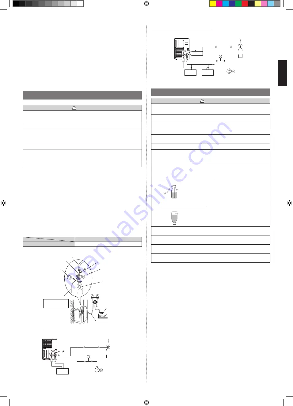
Simultaneous operation multi type

Outdoor unit

Indoor unit

Vacuum pump

Pressure gauge

Pressure regulating valve

Nitrogen

5.6. Additional charging

 CAUTION

Do not turn on the power unless all operations are complete.

After evacuating the system, add refrigerant.

Do not charge the system with a refrigerant other than R410A.

Always keep to the limit on the total amount of refrigerant. Exceeding the limit on the 
total amount of refrigerant will lead to malfunction during charging of refrigerant.

Do not reuse recovered refrigerant.

Use an electronic scale to measure the charging amount of refrigerant. 
Adding more refrigerant than the speci

fi

 ed amount will cause a malfunction.

Add refrigerant by charging the system with the refrigerant in the liquid state.

When charging the refrigerant, take into account the slight change in the composition 
of the gas and liquid phases, and always charge from the liquid phase side whose com-
position is stable. Adding refrigerant through the gas pipe will cause a malfunction.

Check if the steel cylinder has a siphon installed or not before 

fi

 lling. (There is an indi-

cation “with siphon for 

fi

 lling liquid” on the steel cylinder.)

Filling method for cylinder with siphon

Set the cylinder vertical and 

fi

 ll with the liquid.

(Liquid can be 

fi

 lled without turning bottom up with the 

siphon inside.)

Liquid

Gas

R410A

Filling method for other cylinders

Turn bottom up and 

fi

 ll with liquid.

(Be careful to avoid turning over the cylinder.)

Liquid

Gas

R410A

Be sure to use the special tools for R410A for pressure resistance and to avoid mixing 
of impure substances.

If the units are further apart than the maximum pipe length, correct operation cannot be 
guaranteed.

Make sure to back closing valve after refrigerant charging. Otherwise, the compressor 
may fail.

Minimize refrigerant release to the air. Excessive release is prohibited under the Freon 
Collection and Destruction Law.

5.6.1. If additional refrigerant is required

•  When the piping is longer than chargeless piping length, additional charging is neces-

sary.

 1)  Remove the charging cap from the liquid pipe.
 2)  Attach a charging hose to the refrigerant cylinder, and connect it to the charging 

port.

 3)  Add refrigerant by calculating the additional refrigerant volume in accordance with 

the table below.

 4)  Remove the charging hose and install the charging cap.
 5)  Remove the body caps (gas pipe, and liquid pipe), and open the valves.
 6)  Close the body caps.

*  Tighten the body caps and charging caps to the torque values speci

fi

 ed in the Table A.

To open and close the valves,
Use an M5 hexagon wrench for liquid pipes.
Use an M10 hexagon wrench for gas pipes.

•  After connecting the pipes, perform a sealing test.

•  Make sure that the 3-way valves are closed before performing a sealing test.

•  Pressurize nitrogen gas to 4.15 MPa to perform the sealing test.

•  Add nitrogen gas to both the liquid pipes and the gas pipes.

• Check all 

fl

 are connections and welds. Then, check that the pressure has not 

decreased.

•  Compare the pressures after pressurizing and letting it stand for 24 hours, and check 

that the pressure has not decreased.
* When the outdoor air temperature changes 5 °C, the test pressure changes 
0.05 MPa. If the pressure has dropped, the pipe joints may be leaking.

•  If a leak is found, immediately repair it and perform the sealing test again.

•  After completing the sealing test, release the nitrogen gas from both valves.

•  Release the nitrogen gas slowly.

5.5. Vacuum process

 CAUTION

Perform a refrigerant leakage test (air tightness test) to check for leaks using nitrogen 
gas while all valves in the outdoor unit are closed. (Use the test pressure indicated on 
the nameplate.)

Be sure to evacuate the refrigerant system using a vacuum pump.

The refrigerant pressure may sometimes not rise when a closed valve is opened after 
the system is evacuated using a vacuum pump. This is caused by the closure of the 
refrigerant system of the outdoor unit by the electronic expansion valve. This will not 
affect the operation of the unit.

If the system is not evacuated suf

fi

 ciently, its performance will drop.

Use a clean gauge manifold and charging hose that were designed speci

fi

 cally for use 

with R410A. Using the same vacuum equipment for different refrigerants may damage 
the vacuum pump or the unit.

Do not purge the air with refrigerants, but use a vacuum pump to evacuate the system.

(1)   Check that the valves are closed by removing the blank caps from the gas and 

liquid pipes.

(2)   Remove the charging port cap, and connect the gauge manifold and the vacuum 

pump to the charging valve with the service hoses.

(3)  Vacuum the indoor unit and the connecting pipes until the pressure gauge 

indicates –0.1 MPa (–76 cmHg).

(4)   When –0.1 MPa (–76 cmHg) is reached, operate the vacuum pump for at least 

60 minutes.

(5)  Disconnect the service hoses and 

fi

 t the charging port cap to the charging valve to 

the speci

fi

 ed torque. (Refer to below table)

(6)  Remove the blank caps, and fully open the 3-way valves with a hexagon wrench 

[Torque: 6 to 7 N·m (60 to 70 kgf·cm)].

(7)   Tighten the blank caps of the 3-way valve to the speci

fi

 ed torque. (Refer to Table A 

on page 7.)

Tightening torque [N·m (kgf·cm)] 

Charging port cap

10 to 12 (100 to 120)

Service hose

Service hose with valve core

Charging port

Blank cap

Hexagon wrench

Connecting pipe

Gauge manifold

Vacuum pump

Charging port cap

3-way valve

Use a 4 mm 
hexagon wrench

Single type

Pressure regulating valve

Pressure gauge Nitrogen

Indoor unit

Outdoor unit

Vacuum pump

9380545231_IM.indb   8

9380545231_IM.indb   8

7/14/2017   8:53:12 AM

7/14/2017   8:53:12 AM

Summary of Contents for AOYG72LRLA

Page 1: ...amente para personal de servicio autorizado MANUALE D INSTALLAZIONE UNITÀ ESTERNA A uso esclusivo del personale tecnico autorizzato ΕΓΧΕΙΡΙΔΙΟ ΕΓΚΑΤΑΣΤΑΣΗΣ ΕΞΩΤΕΡΙΚΗ ΜΟΝΑΔΑ Μόνο για εξουσιοδοτημένο τεχνικό προσωπικό MANUAL DE INSTALAÇÃO UNIDADE EXTERIOR Somente para o pessoal do serviço técnico autorizado РУКОВОДСТВО ПО УСТАНОВКЕ ВНЕШНИЙ МОДУЛЬ Только для авторизованного обслуживающего персонала K...

Page 2: ...used as the packaging material away from young children CAUTION Indicates a potentially hazardous situation that may result in minor or moderate injury or damage to property For the air conditioner to work appropriately install it as written in this manual This product must be installed by qualified personnel with a capacity certification of handling refrigerant fluids Refer to regulation and laws...

Page 3: ... the area If the refrigerant comes in contact with a flame it produces a toxic gas The basic installation work procedures are the same as conventional refrigerant models However pay careful attention to the following points Since the working pressure is 1 6 times higher than that of conventional refrigerant R22 models some of the piping and installation and service tools are special See the table ...

Page 4: ...reception interference or radio noise Even if they are installed more than 1 m apart you could still receive noise under some signal conditions If children under 10 years old may approach the unit take preventive measures so that they cannot reach the unit Keep the length of the piping of the indoor and outdoor units within the allowable range For maintenance purposes do not bury the piping 3 2 Dr...

Page 5: ... using them the cabinet may be damaged or deformed The center of gravity of the outdoor unit is shifted to the right Be careful not to tilt to the heavy side causing it to fall To prevent accidents caused by the unit swinging or falling down do not apply any impact to the unit when it is hanging When hoisting do not hook the rope to the thermistor holder on the back of the outdoor unit Protective ...

Page 6: ...ct the pipe size in accordance with local rules 1 Allowable tensile stress 33 N mm2 2 Allowable tensile stress 61 N mm2 3 Endurance pressure of the pipes 4 2MPa 4 2 Protection of pipes Protect the pipes to prevent the entry of moisture and dust Especially pay attention when passing the pipes through a hole or connecting the end of a pipe to the outdoor unit Location Working period Protection metho...

Page 7: ... 4 3 2 Simultaneous operation multi type installation Triple type Capacity Btu h class 72 000 90 000 Main piping mm in Liquid pipes 12 70 1 2 Gas pipes 22 22 7 8 25 40 1 Branch piping mm in Liquid pipes 9 52 3 8 Gas pipes 15 88 5 8 Piping length m m Max piping length L1 L2 L3 L4 1 Pre charge length 100 30 100 30 1 Refer to View in Triple type of 4 3 2 Simultaneous operation multi type installation...

Page 8: ... side and gas side pinch pipe and vent the gas inside the pinch pipe 3 After all the gas is vented melt the brazing filler metal on connecting part using a torch and remove the pinch pipe 3 way valves Pinch pipes End of pinch pipes 5 3 4 Pipe connection CAUTION Seal the pipe route hole with putty locally purchased such that there are no gaps Small insects or animals that are trapped in the outdoor...

Page 9: ... perform a sealing test Make sure that the 3 way valves are closed before performing a sealing test Pressurize nitrogen gas to 4 15 MPa to perform the sealing test Add nitrogen gas to both the liquid pipes and the gas pipes Check all flare connections and welds Then check that the pressure has not decreased Compare the pressures after pressurizing and letting it stand for 24 hours and check that t...

Page 10: ...40 Example 1 L2 10 m L1 30 m L3 7 m Liquid pipe diameter mm Piping length m Coefficient 12 70 30 A 30 9 52 17 B 17 6 35 0 C 0 Additional charging amount Applying the formula 30 x 110 17 x 50 0 x 30 3300 850 The additional charging amount is 850 g Liquid pipe diameter mm Piping length m Coefficient 12 70 10 A 10 9 52 15 B 15 6 35 0 C 0 Additional charging amount Applying to the formula 10 x 110 15 ...

Page 11: ... install the electrical box cover on the unit An improperly installed service panel can cause serious accidents such as electric shock or fire through exposure to dust or water If the supply cable is damaged it must be replaced by the manufacturer its service agent or similarly qualified persons in order to avoid a hazard CAUTION The primary power supply capacity is for the air conditioner itself ...

Page 12: ...e blue wire to the N terminal 6 4 2 Connection cable preparation Keep the earth wire longer than the other wires Earth wire 30 mm Power supply cable or Connection cable 35 mm 6 4 3 Wiring procedure 1 Remove the service panel the terminal cover and connect the wires to the terminal in accordance with the terminal nameplate Fig A Fig B 2 Secure the cables using the cable clamps under the terminal bl...

Page 13: ...ric shock CAUTION Once refrigerant charging is completed be sure to open the valve prior to performing the local settings Otherwise the compressor may fail Discharge any static electricity from your body before touching the push buttons Never touch any terminal or pattern of any parts on the control board Remove the front panel of the outdoor unit to access the print circuit board of the display u...

Page 14: ...just LED lamp as shown in below figure PEAK CUT L4 L5 L6 Level 1 Low Blink Level 2 Lower Blink Sign Lights off The noise of Level 2 is lower than the one of Level 1 6 Press ENTER button SW109 and fix it PEAK CUT L4 L5 L6 Level 1 Low Level 2 Lower Sign Lights off Lights on 7 Return to Operating status display Normal operation by pressing EXIT button SW112 In case of missing how many times SELECT an...

Page 15: ...Low noise mode Off Normal operation Input Signal Low noise mode On On Off Off 10 1 3 Peak cut mode CN132 Operation that suppressed the current value can be performed by means of the connected unit The air conditioner is set to the Peak cut mode by applying the contact input of a commercial On Off switch to a connector on the outdoor control PC board Set the Peak cut mode level refer to 9 1 Functio...

Page 16: ... of various pipes flange connection brazing Is the heat insulation done completely Gas pipe liquid pipe drain hose extension on indoor unit side etc Is the water discharging from drain without any problems Are the cables connected correctly Are the cables as per specifications Is the earth wire connected accurately Are there any obstacles blocking the suction gate and outlet of the indoor outdoor ...

Page 17: ... Discharge temp sensor 1 error 2 7 2 Compressor temp sensor error Compressor temp sensor 1 error 2 7 3 Outdoor unit Heat Ex sensor error Heat Ex middle temp sensor error 2 7 3 Outdoor unit Heat Ex liquid temp sensor error 2 7 4 Outdoor temp sensor error Outdoor temp sensor error 2 7 7 Heat sink temp sensor error Heat sink temp sensor error 2 8 4 Current sensor error Current sensor 1 error stoppage...

Page 18: ...ssor is operating the compressor will stop then start again in about 3 minutes 4 LED display will change as shown below about 3 minutes after the compressor starts Fully close the 3 way valve on the liquid pipe side at this stage POWER MODE ERROR PUMP DOWN LOW NOISE PEAK CUT L1 L2 L3 L4 L5 L6 Sign Lights off Lights on If the valve on the liquid pipe side is not closed the pump down cannot be perfo...

Reviews: