41S_Rev00
35
Basic Operation
4.
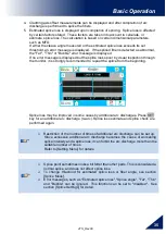
Cladding axis offset measurements can be displayed and after completion of arc
discharge is performed to splice the fibers.
5.
Estimated splice loss is displayed upon completion of splicing. Splice loss is affected
by certain factors stated. These factors are taken into account to calculate, or
estimate, splice loss. The calculation is based on certain dimensional parameters,
such as MFD.
If either the cleave angle measured or the estimated splice loss exceeds its set
threshold, an error message is displayed. If the spliced fiber is detected as abnormal,
the "Fat", "Thin" or "Bubble" error message is displayed.
If no error message is displayed but the splice looks poor by visual inspection through
the monitor, it is strongly recommended to repeat the splice from the beginning.
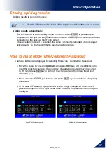
Splice loss may be improved in some cases by additional arc discharges. Press SET
key for an additional arc discharge (re-arc). Splice loss estimate and splice check are
performed again.
Restriction of the number of times of additional arc discharge can be set up.
Since excessive additional arc discharge becomes the cause of worsening
splice intensity and a splice loss, it can forbid the arc discharge more than the
suitable number of times.
Refer to [Setting Menu] for details.
Splice point sometimes looks a bit fatter than other parts. This is considered a
normal splice, and does not affect splice loss.
To change threshold for estimated splice loss or fiber angle, see section
[Splice Mode].
Error messages, such as "Estimated splice loss", "Splice angle", "Fat", "Thin"
and "Bubble" can be ignored. This function can be set to "disabled". See
section [Splice Settings] for detail.

