5
PARAMETERS
5-4
5-2) List of parameters
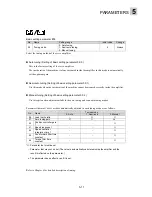
n
List of parameters of FALDIC-
β
(1)
No.
Name
Setting range
Initial value Change Page
Basic settings
01
Command pulse correction
α
1 to 32767 (in 1 increments)
8
Always
5-6
02
Command pulse correction
β
1 to 32767 (in 1 increments)
1
Always
5-6
03
Pulse string input form
0: Command pulse/command sign,
1: Forward/reverse rotation pulse,
2: Two signals with 90-degree phase
difference
1
Power
5-8
04
Direction of rotation switch
0: Positive direction: Forward rotation
(CCW),
1: Positive direction: Reverse rotation (CW)
0
Power
5-10
05
Tuning mode
0: Auto tuning,
1: Semi-auto tuning,
2: Manual tuning
0
Always
5-11
06
Load inertia ratio
0.0 to 100.0 times (in 0.1 increments)
5. 0
Always
5-12
07
Auto tuning gain
1 to 20 (in 1 increments)
10
Always
5-13
08
and
09
Not used
-
0
-
5-14
System settings
10
CONT 1 signal allocation
1 [RUN]
Power
11
CONT 2 signal allocation
2 [RST]
Power
12
CONT 3 signal allocation
0
Power
13
CONT 4 signal allocation
0
Power
14
CONT 5 signal allocation
0 to 10 (in 1 increments)
0
Power
5-16
15
OUT 1 signal allocation
1
Alarm detect:
a-contact
Power
16
OUT 2 signal allocation
0 to 5 (in 1 increments)
0
Power
5-16
17
Output pulse count
16 to 16384 [pulse] (in 1 increments)
2048
Power
5-32
18
Phase-Z offset
0 to 65535 [pulse] (in 1 increments)
0
Power
5-33
19
Zero deviation width
1 to 10000 [pulse] (in 1 increments)
200
Always
5-34
20
Deviation limit width
10 to 65535 [x 100 pulse] (in 1 increments)
10000
Always
5-35
21
Zero speed width
10 to 5000 [r/min] (in 1 increments)
50
Always
5-36
22
Positioning end judgment time
0.000 to 1.000. sec. (in 0.001 increments)
0.000
Always
5-37
23
Max. current limit
0 to 300 % (in 1 increments)
300
Always
5-37
24
Undervoltage alarm detection
0: No detection, 1: Detection
1
Power
5-38
25
Regenerative resistor electronic
thermal calculation
0: Invalid,
1: Valid (optional regenerative resistor (thin
type))
0
*1
Power
5-39
26
Dynamic brake on overtravel
detection valid/invalid
0: Invalid,
1: Valid
0
Power
5-40
27
Parameter write-protection
0: Write-enable, 1: Write-protected
0
Always
5-41
28
Keypad panel initial display
0 to 11 (in 1 increments)
0
Power
5-41
29
Speed setting (for test operation) 1 to 5000 [r/min] (in 1 increments)
100
Always
5-42
30
Acceleration / deceleration time
(for test operation)
0.000 to 9.999 sec. (in 0.001 increments)
0.100
Always
5-42
31
to
39
Not used
-
0
-
5-43
*1. Set to “1” when thin external regenerative resistor is connected.
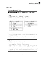
0: Not specified
1: Operation command [RUN]
2: Reset [RST]
3: + overtravel
4: - overtravel
5: Emergency stop [EMG]
6: P-action
7: Deviation clearance
8: External regenerative
9: Anti-resonance frequency
resistor overheat
selection 0
10: Anti-resonance
frequency selection 1
0: Not specified
1: Alarm detection: a-contact
2: Alarm detection: b-contact
3: Dynamic brake
4: Overtravel detection
5: Forced stop detection
Summary of Contents for GYN101CAG-G09
Page 1: ...FUJI AC SERVO SYSTEM USER S MANUAL MEH395 ...
Page 2: ......
Page 10: ......
Page 20: ...1 Outline 1 10 MEMO ...
Page 21: ...2 1 Servomotor 2 2 Servo amplifier INSTALLATION ...
Page 32: ...2 INSTALLATION 2 12 MEMO ...
Page 46: ...3 WIRING 3 14 MEMO ...
Page 52: ...3 WIRING 3 20 MEMO ...
Page 64: ...3 WIRING 3 32 MEMO ...
Page 65: ...4 1 Test operation in two stages 4 2 First stage 4 3 Second stage TEST OPERATION ...
Page 70: ...4 TEST OPERATION 4 6 MEMO ...
Page 85: ...PARAMETERS 5 5 15 MEMO ...
Page 132: ...6 ADJUSTMENT OF SERVO 6 8 MEMO ...
Page 164: ...8 KEYPAD PANEL 8 18 MEMO ...
Page 186: ...9 INSPECTION AND MAINTENANCE 9 22 MEMO ...
Page 226: ...11SPECIFICATIONS 11 14 MEMO ...
Page 234: ...11SPECIFICATIONS 11 22 Servo amplifier Unit mm Unit mm Unit mm ...
Page 235: ...APPENDIXES Inertia moment calculation Load torque Timing chart ...
Page 250: ...APPENDIXES Appendix 16 MEMO ...
Page 251: ...APPENDIXES Appendix 17 MEMO ...


