WIRING
3
3-25
n
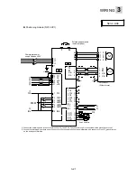
Positioning module (NP1F-MP2)
Servo side
U
V
W
1 U
2 V
3 W
4 E
7
CA
8
*CA
21
*CB
20
CB
M
1
P5
2
M5
5
SIG+
6
SIG-
P5 1
M5 2
SIG+
5
SIG- 6
PG
FZ 25
M5 26
L1
L2
L3
FFA 9
FFB 11
*FFB 12
FFZ 23
*FFZ 24
*FFA 10
CN1
CN1
CN1
CN1
CN2
CN2
CN2
CN2
1
P24
2
CONT1
5 CONT4
3
CONT2
6 CONT5
14
M24
4
CONT3
P24
OUT1 15
OUT2 16
RDY 17
PSET 18
P24
DB
19
PPI
P
⑤
⑥
⑦
⑧
⑨
⑩
M5 13
*3
*1
*1
*1
M24
⑪
⑫
DC24V
①
②
③
④
*1
Servo amplifier
Commercial power
supply 3-phase 200V
External regenerative resistor
(Option)
Servomotor
(Without brake)
*1: Connect the shielding wires to the connector shell of CN1 and CN2. The connector shell is connected with the grounding terminal.
*2: Ground the shielding wire at both ends. (Connect it to the connector shell on the amplifier side, and connect it to the FG (ground) termin
on the pulse generator side.
*3: Operation can be made even if these terminals are left open.
Summary of Contents for GYN101CAG-G09
Page 1: ...FUJI AC SERVO SYSTEM USER S MANUAL MEH395 ...
Page 2: ......
Page 10: ......
Page 20: ...1 Outline 1 10 MEMO ...
Page 21: ...2 1 Servomotor 2 2 Servo amplifier INSTALLATION ...
Page 32: ...2 INSTALLATION 2 12 MEMO ...
Page 46: ...3 WIRING 3 14 MEMO ...
Page 52: ...3 WIRING 3 20 MEMO ...
Page 64: ...3 WIRING 3 32 MEMO ...
Page 65: ...4 1 Test operation in two stages 4 2 First stage 4 3 Second stage TEST OPERATION ...
Page 70: ...4 TEST OPERATION 4 6 MEMO ...
Page 85: ...PARAMETERS 5 5 15 MEMO ...
Page 132: ...6 ADJUSTMENT OF SERVO 6 8 MEMO ...
Page 164: ...8 KEYPAD PANEL 8 18 MEMO ...
Page 186: ...9 INSPECTION AND MAINTENANCE 9 22 MEMO ...
Page 226: ...11SPECIFICATIONS 11 14 MEMO ...
Page 234: ...11SPECIFICATIONS 11 22 Servo amplifier Unit mm Unit mm Unit mm ...
Page 235: ...APPENDIXES Inertia moment calculation Load torque Timing chart ...
Page 250: ...APPENDIXES Appendix 16 MEMO ...
Page 251: ...APPENDIXES Appendix 17 MEMO ...


